


一提起烟火晚会,脑子里总会浮现出数不清的浪漫画面。
人生也不过活那几个瞬间。总感觉只要在绚烂的烟花下,一切都值得了。
“走吧,烟火晚会必须看。”不在富士山下看一场冬日烟火,我会后悔一辈子的。


我之前一直不理解,为什么陈奕迅说“要想拥有必须先懂失去怎么接受”。
试着接受一个人的离开大概是常态。
毕竟,那些竭尽全力的事情,结果往往不尽如人意。反倒是那些出乎意料顺利的事,才是真正实现的目标。
如果一件事情有百分百的把握,就变得索然无味了。
代码我有三不写
第一:不能复制的我不写,因为别人的轮子写好了我干嘛不用
第二:不让我用Chatgpt”辅助”的我不写,因为基础的东西我都会,写了没意义
第三:太难写的我不写,因为我还没有到那个境界,写不明白

当代人赶车状态就是:越不着急,越容易错过。越着急,那更容易错过。
只有一时着急一时从容才不会错过。
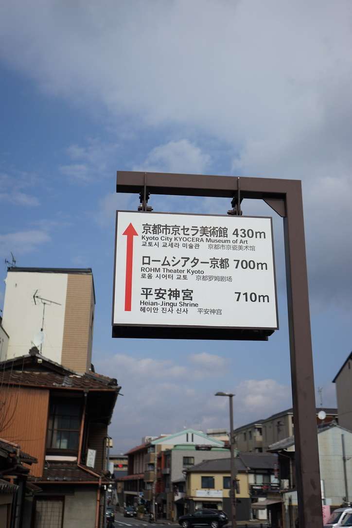
这次在京都赶车,我与友人前一秒还在百米冲刺,下一秒就被路边的免费杂志硬控了3分钟。
就算是错过了巴士,我也不是很后悔了。只不过有些遗憾罢了,毕竟大多数事情都不是我能决定的,是与生俱来的罢了。


为什么要坐日本的夜间大巴,为什么不坐新干线,为什么不坐飞机?
为了看这个烟火表演,我们必须在河口湖住一晚上。
为了能在京都多一个美好的下午,坐夜间巴士是最节约时间的。
一个冷知识是,新干线的价格比飞机还要贵。
但是京都和河口湖地区都没有飞机场,想要从京都->富士山最方便的就是夜间大巴了。

晚上出发去车站之前,在酒店的公共厕所完成了所有洗漱工作,上了大巴之后就是美美睡觉了。
日本的夜间大巴还是蛮舒服的。也可能是我选择了价格最高的一班(也才36,800yen四个人)。
座位是分成三列,之间有小帘子遮挡,也有充电口,这还要什么自行车。
唯一想要吐槽的就是巴士的灯竟然在上车一个多小时之后才关掉,而且司机一直在广播,也听不清楚他说了个啥,简直是噪音+光污染。

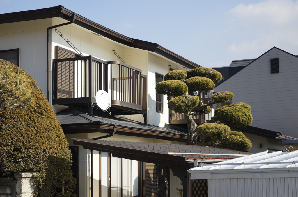
约莫早上七点,巴士就快抵达富士吉田市了。陆陆续续有乘客下车,我们是最后一个停靠点,河口湖站。

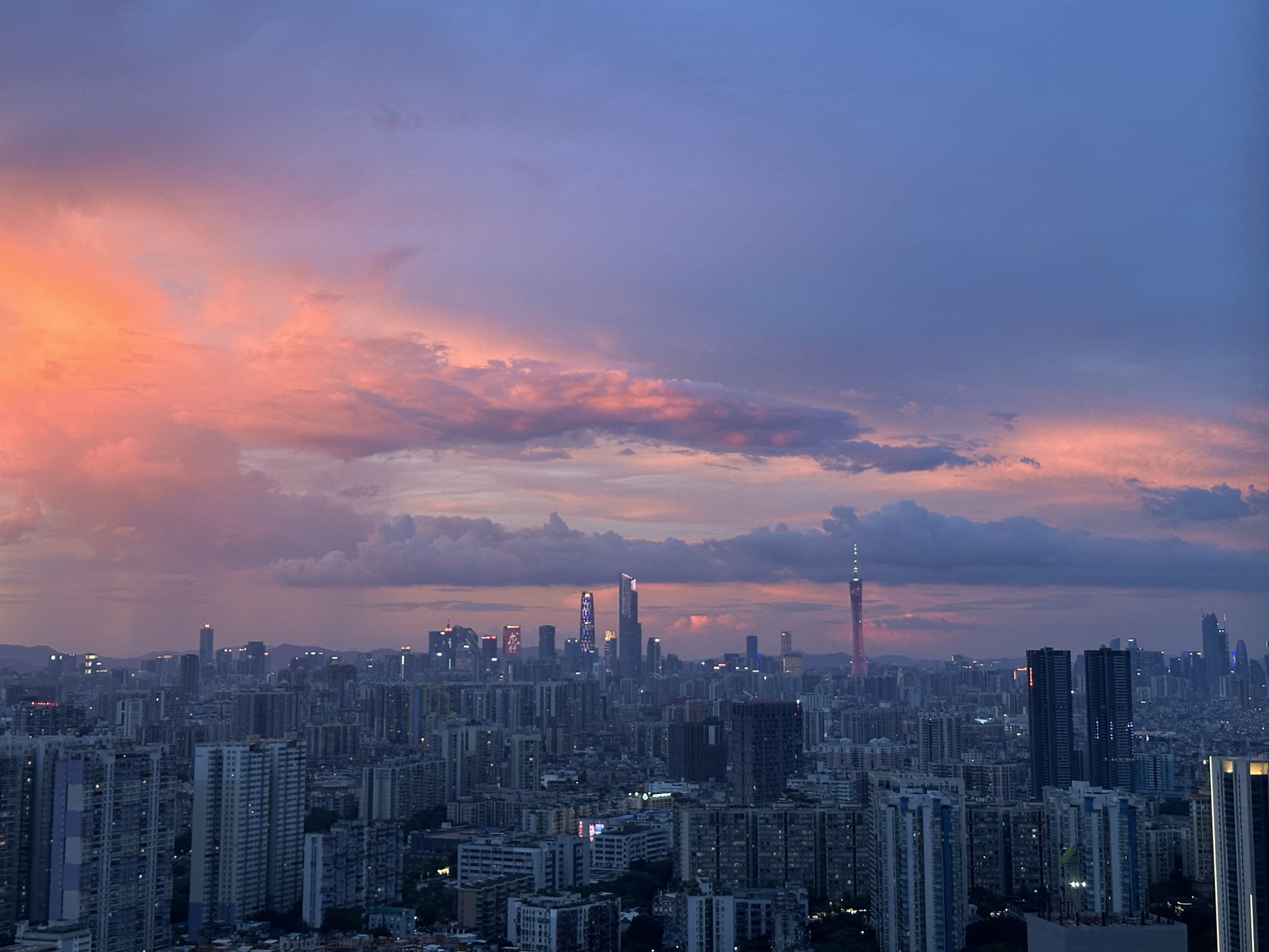
下了车,富士山就在眼前。
但不知为何我却想起傍晚黄昏的路灯,摇曳的树梢,漂泊的人影,还有那个曾经想要和我在富士山下听富士山下的你。意义不重要,或许是在错的时间遇到了对的人。也可能人是错的,时间是对的。也可能都错了,或者都对了,都不重要了。我们活得太匆忙,对情感的分辨已不再细致追问。
富士山永远都在那里,你可以看到它但是不能搬走它。
想起以前的一个朋友,大一的时候在学校的咖啡厅认识他。这个哥们跟我们不一样,他是专门研究算命的。他在咖啡厅有他固定的位置,不买饮品,就光在那看易经。每次坐在他对面,总感觉他在对我们这些苦读高等数学的人说:“大春,千万别再学高数了,你学不会的“。我有很多次想拜托他帮忙算算我这学期末高数能考多少分,但是转念一想,反正再这样下去他的高数成绩肯定不比我高,何必寄托于玄学呢。
后来海南发生了一个红衣女在阳台围栏外面跳舞然后坠楼的诡异视频,据说是集齐了金木水火土元素,搞的是什么邪术献祭。我想起这个哥们,于是拜托发给他,他说假得很,狗都不信。

有目的的人生才会迷路,漫无目的的人生才不是虚度。种下一棵树最好的时间是十年前,其次是九年前。
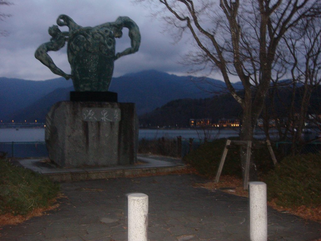
旅行最有趣的部份在于他的随机性。在河口湖站寄存行李的时候,偶然发现一个风景极好的自助餐厅。


我这个人很喜欢蓝调时刻。每次看到蓝色的天空,脑子里总是自动播放德彪西的月光。
在那一刻的恍惚之间,不由自主将眼前的照片拍下。却忽然察觉,我似乎在做梦,眼前的一切伴随着我声嘶力竭地呐喊消失。富士山下的人们,结局总是如此。

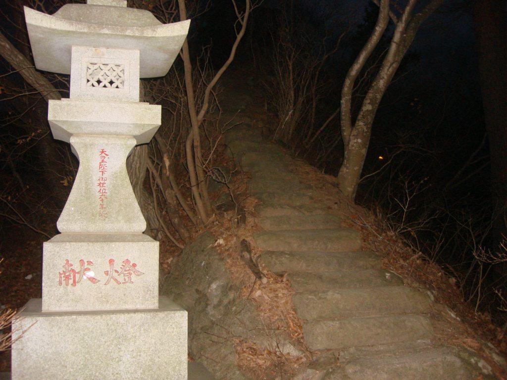
随着人群一路走到新倉山淺間公園,山不高,很好爬。
一边吃着草莓就爬上去了。
只可惜这个季节没有樱花。毕竟,没有一件事是十全十美的,处处充满妥协。


这个机位应该也算是游客标准照了,是个人都能拍得很好看。
这一天天气很好,可以看到富士山的全貌。
但是人潮汹涌,想必是富士地区游客最密集的景点之一了。


我真的很喜欢下面拍的这张照片,你们觉得呢。


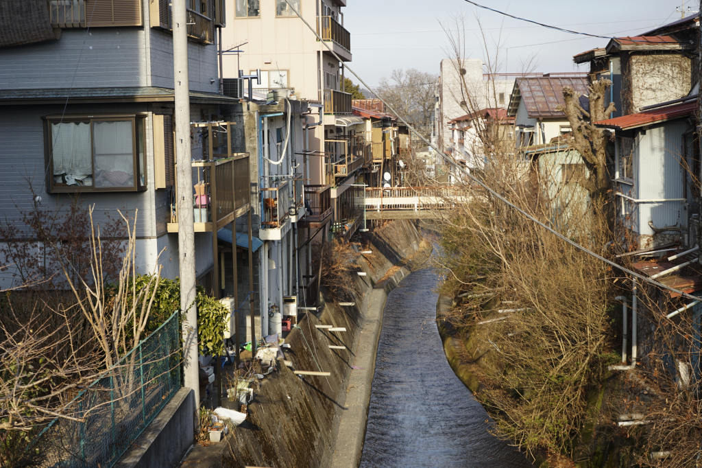
可惜天公不作美,下山之后云层立马将富士山遮盖。
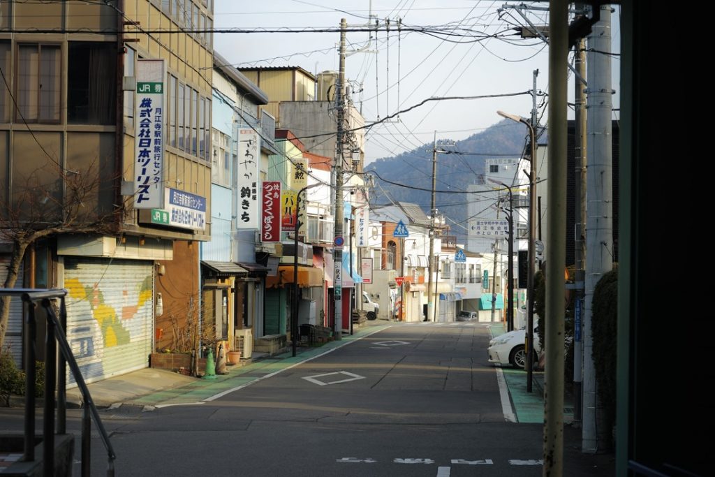
心心念念的「本町通り」街道拍摄就此作罢。
只好在google maps上找一张图来弥补遗憾了。

沿着本町通り一路向富士山的方向走,我与友人来到了一家老奶奶自家经营的小餐馆。
进门之前,由于已经是下午两点多了,老板还在犹豫是否要接客。看到我们一行人饥肠辘辘,加之是亚洲脸孔的缘故吧,就破例最后接待我们一桌,让我们我门口稍等。
就这个时候,一群欧洲脸孔的小哥也走了进来,由于语言不通,老板意思应该是不招待了,但是双方貌似都没懂什么意思。搞笑的一幕发生了,只听见欧洲小哥对我说,“I hate racist, I dont Like her!”,然后骂骂咧咧的离开了。真是大误会。
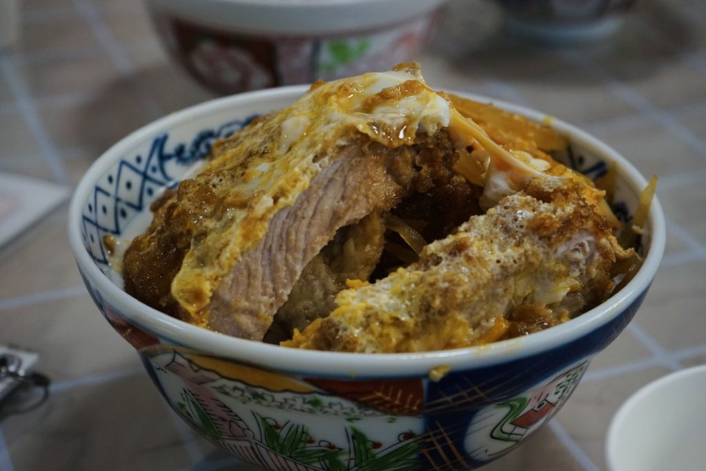
饭菜的份量很足,不用担心不够吃。
乌冬面是免费续的,尽管你点了饭,也可以让老板给你上免费的乌冬面。
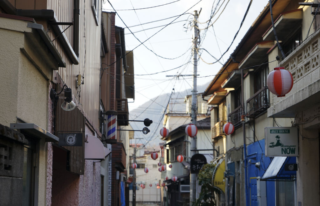
漫步在富士吉田市。


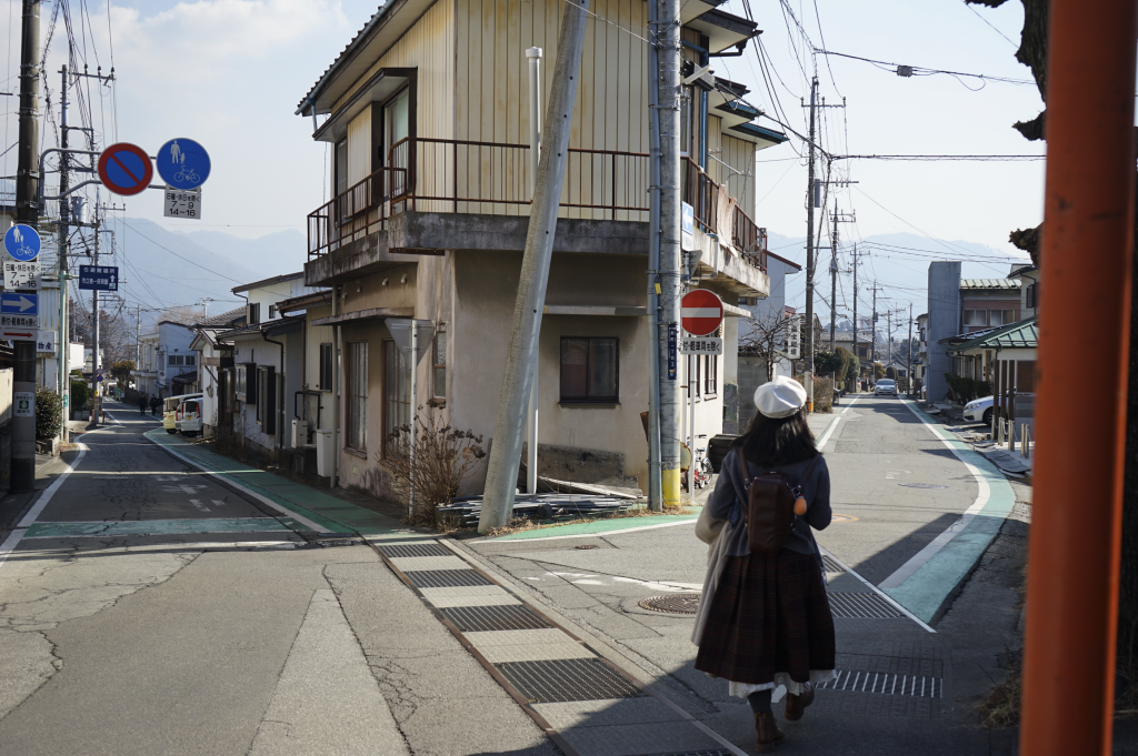

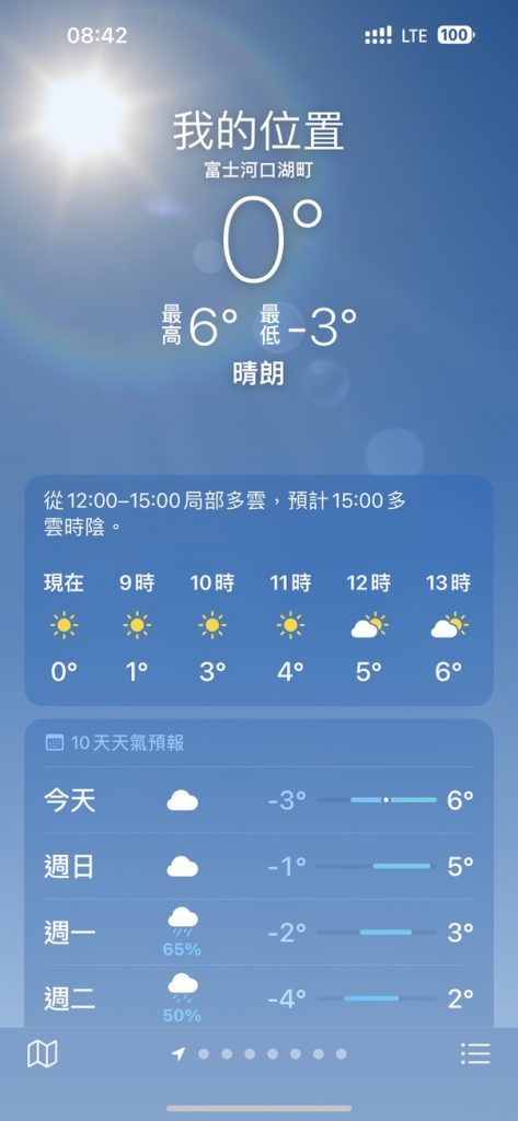
日本的冬天其实不冷。虽然手机上显示温度只有0度,但是心是暖的。
快进到我下雪天穿短裤也不在怕的。


说说这次烟火晚会吧。
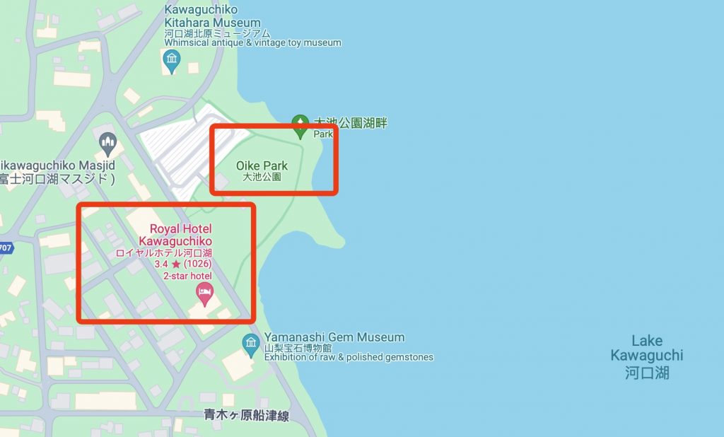
地点是在河口湖的大池公园。由于我的先见之明,我提前一个多月订下了位于烟火发射地仅一步之遥的温泉酒店。烟火晚会结束后看着路人赶车回东京狼狈的样子真的很愉悦。
回到酒店稍作整顿后,出门环湖骑行。
此时距离烟火晚会还有几个小时,天色也渐渐转为蓝调。我沉浸其中,以至于忘记拍照。下面是友人B用胶卷拍摄的。我很喜欢,Ins @dokidoki_yukina 。
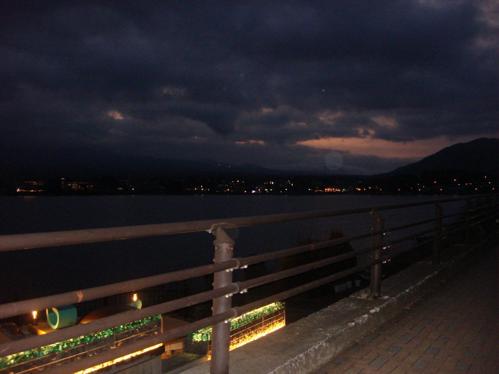


烟火转瞬即逝,却已是永恒。


小时候看动漫时,对烟火晚会的滤镜就是,烟火晚会之下的人们都会经历一生难忘的时刻。


当最后一束烟火绽放,一切都没有改变,改变的只有相机电池的电量,还有随之而来的空腹感。
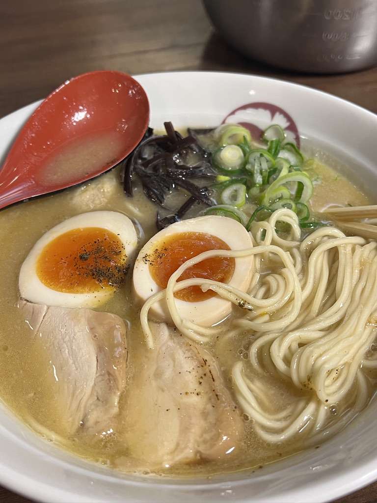
日本的泡面真的非常好吃,尤其是「一燈」,强烈推荐。只可惜香港和大陆都没得卖,只能通过海淘了。


日本的酒店蛮有意思的。
如果要我一个词总结日本,我会说:「干净」。
看到Ins上有一个搞笑视频,内容是将他花了 2000$ 坐飞机过来吃价值 1$ 的便利店饭团,吃得津津有味。底下评论日本最“邋遢”的食物都要比美国的“健康食品”干净。
另外值得一提的事,日本的酒店是按照人头来计算价格的。
即使房间住得下三个人,两个人和三个人入住的价格也是截然不同的。
看到社交平台上有人讨论过这个问题,如果偷偷带一个人进来住会怎么样呢?
有的人说严重的可能会被遣返回国,不知道是不是真的。
毕竟少缴了一份酒店税,四眼仔肯定不高兴啦。
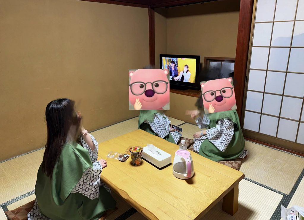
跪在榻榻米上堪比军训。
综合来看,我发现日本无论是饭店还是日式家庭,“坐”这个行为幅度是很大的。如果你是低血糖,这一起一坐恐怕是需要特别注意的。

这个拉面泡面真的比国内拉面馆要好吃很多。
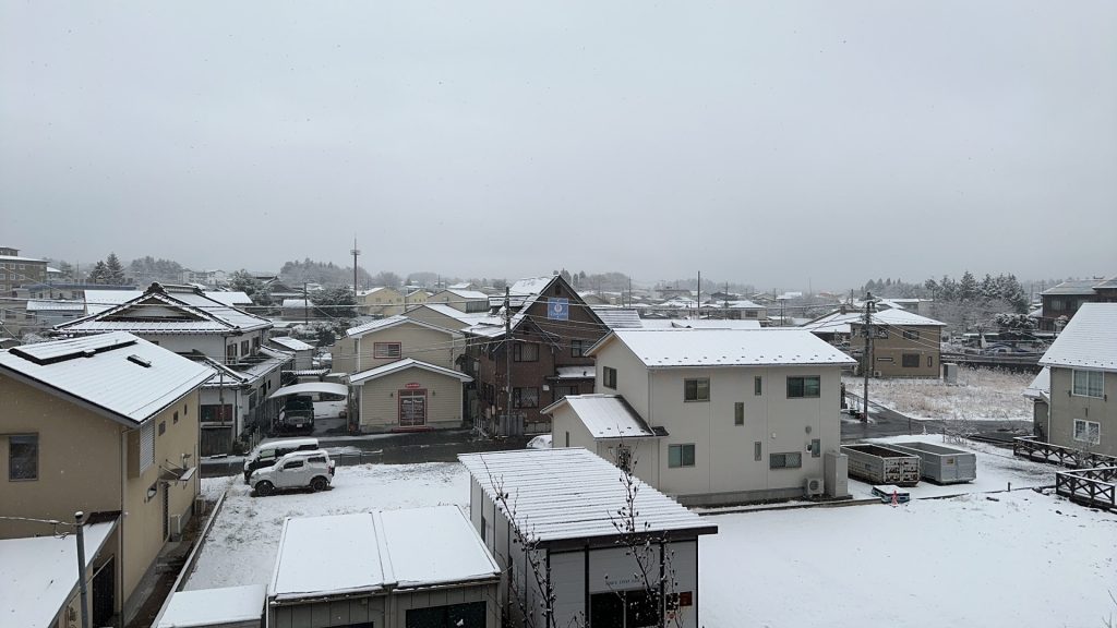
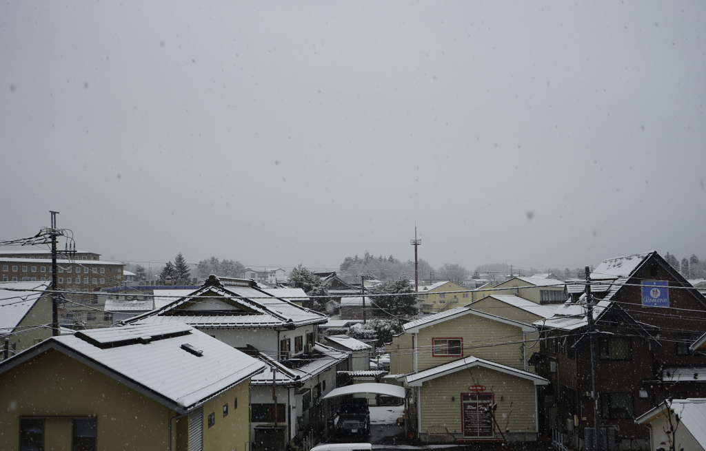
第二天一大早,友人B就喊我们起床了。这一幕仍然记忆犹新,“快看,窗外下雪啦!”
拖延症。
尽管知道10点就要到车站,再不出门就真的没时间散步了。
想起来,平时也是如此。尽管已经拖着一身疲惫回到家,嘴上喊着洗澡啦,却依旧抱着手机拖延个十几分钟。
手机那头的人也许也是如此吧。
以前也许会责备,但是实际上,批判每个阶段的自己是不对的,更何况是别人。每个人正在经历的阶段都不同,小时候觉得背两页课文,天都要塌下来了。现在回看也只会嘲笑自己太脆弱。
最终我们也是拖延到了真的要去赶车了,才出门check out。


接下来,就是去东京,和03年的寡姐一起迷失在下雨的东京繁寂的街头了。
谢谢你读到这里,感谢。

声を聞くだけで幸せになるの
こんな私でも
魔法のような優しいあなたの声
今夜も思い出す
柔らかな明かり灯し眠れば
心地よい風が意識さらっていく…
愛してるよ
夢の中で待ってて
傷付いた羽根を癒やすのは
今でもあなただけなの
今夜もまた会いたい
初めてあなたと出逢えた日のこと
今も覚えてる
都会の片隅で起きた奇跡
星が落ちてきたの
それぞれに過ぎてゆく毎日が
あの日からふたり引き離そうとも…
愛してるよ
あなたが誰といても
離れても 時が過ぎても
心を許せた人は
今もあなただけなの
愛してるよ
夢の中で待ってて
目を閉じて今すぐ行くから
誰より優しい声と
愛しいその眼差しに
今夜もまた 会いたい
标签 :入门/Shader/曲面细分着色器/Displacement贴图/LOD/平滑轮廓/Early Culling
tessellation(镶嵌)一词是指一大类设计活动,通常是指在平坦的表面上,用各种几何形状的瓷砖相邻排列以形成图案。它的目的可以是艺术性的或实用性的,很多例子可以追溯到几千年前。 — Tessellation, Wikipedia, accessed July 2020.
本文主要參考:
游戏开发中的曲面细分一般是在一个三角形平面(或者是Quad)中做细分(增加顶点数量),然后用Displacement贴图来做顶点位移,或者是用本文实现的Phong细分或者PN triangles细分来做顶点位移。
Phong细分不需要知道相邻的拓扑信息,仅仅用插值计算,比PN triangles等算法效率更高。GAMES101上提到的Loop and Schaefer利用低度数四边形曲面近似Catmull-Clark曲面,这些方法输入的多边形都被一个多项式曲面替代。而本文的Phong细分不需要任何修正额外的几何区域的操作。
这章内容是曲面细分在渲染管线流程的介绍。
曲面细分着色器位于顶点着色器之后,且曲面细分分为三个步骤:Hull、Tesselllator和Domain,其中Tessellator不可编程。

曲面细分的第一个步骤是曲面细分控制着色器(也称为Tessellation Control Shader,TCS),这个着色器将会输出控制点和细分因子。这个阶段主要由两个并行的函数组成:Hull Function和Patch Constant Function。

这两个函数都接收一个个的Patch,即一组顶点索引,比如三角形则用三个数字表示顶点的索引。其中一个Patch就可以组成一个片元,比方说一个三角形片元就是由三个顶点索引组成的。
并且,Hull Function每个顶点执行一次,Path Constant Function每个Patch执行一次,前者输出修改后的控制点数据(通常包括顶点位置、可能的法线、纹理坐标等属性),后者则输出整个片元相关的常量数据,即细分因子。细分因子会告诉下一个阶段(镶嵌器Tessellator)如何对每个片元进行细分。
笼统地讲,Hull Function修改每个控制点,而Patch Constant Function确定基于摄像机距离的细分级别。

接下来进入不可编程阶段,镶嵌器(tessellator)。他接收Patch和刚刚得到的细分因子。镶嵌器会为每一个顶点数据生成一个重心坐标(Barycentric coordinates)。

紧接着来到最后一步,域阶段(Domain Stage,也称为Tessellation Evaluation Shader,TES),这是可编程的。这个部分由域函数组成,每个顶点执行一次。接收重心坐标、Patch和Hull Stage中两个函数生成的结果。大多数逻辑都在这个地方编写。最重要的是你可以在这个阶段重新定位顶点,这是曲面细分中最重要的环节。

如果有几何着色器,他将会在Domain Stage后执行。但是如果不用,则来到光栅化阶段。

总结,最开始是顶点着色器。Hull阶段接受顶点数据,决定如何细分Mesh。然后通过tessellator阶段处理细分网格,最后由Domain阶段为片元着色器输出顶点。
这章内容是Unity曲面细分的代码分析,实际例子效果展示和底层原理概述。
首先曲面细分着色器需要使用shader target 5.0。
HLSLPROGRAM
#pragma target 5.0 // 5.0 required for tessellation

#pragma vertex Vertex
#pragma hull Hull
#pragma domain Domain
#pragma fragment Fragment

ENDHLSL经典的流程,顶点着色器将位置和法线信息转为世界空间。然后将输出结果传递到Hull Stage中。需要注意的是,和顶点着色器不同,Hull着色器的顶点使用 INTERNALTESSPOS 语义而不是 POSITION 语义来表示。原因在于Hull不需要将这些顶点位置输出到下一个渲染流程,而是用于自身内部曲面细分的算法,所以会将这些顶点转换到更适合曲面细分的坐标系统。除此之外开发者也能更加清晰区分。
struct Attributes {
    float3 positionOS : POSITION;
    float3 normalOS : NORMAL;
    UNITY_VERTEX_INPUT_INSTANCE_ID
};

struct TessellationControlPoint {
    float3 positionWS : INTERNALTESSPOS;
    float3 normalWS : NORMAL;
    UNITY_VERTEX_INPUT_INSTANCE_ID
};

TessellationControlPoint Vertex(Attributes input) {
    TessellationControlPoint output;

    UNITY_SETUP_INSTANCE_ID(input);
    UNITY_TRANSFER_INSTANCE_ID(input, output);

    VertexPositionInputs posnInputs = GetVertexPositionInputs(input.positionOS);
    VertexNormalInputs normalInputs = GetVertexNormalInputs(input.normalOS);

    output.positionWS = posnInputs.positionWS;
    output.normalWS = normalInputs.normalWS;
    return output;
}
下面是Hull Shader的一些设置参数。
第一行domain是定义曲面细分着色器的域类型,意味着输入输出都是三角形图元。可以选tri(三角形)、quad(四边形)等。
第二行outputcontrolpoints 则表示输出控制点的数量,3对应三角形的三个顶点。
第三行outputtopology表示细分后图元的拓扑结构,triangle_cw意思是输出三角形的顶点按照顺时针排序,正确的顺序可以确保表面正面朝外。triangle_cw(顺时针环绕三角形)、triangle_ccw(逆时针环绕三角形)、line(线段)
第四行patchconstantfunc就是Hull Stage的另外一个函数,输出的是细分因子等常量数据。一个Patch只执行一次。
第五行partitioning,分割模式,指定了如何分配额外的顶点到原始Path图元的边上,这一步可以让细分过程更加的平滑均匀。integer,fractional_even,fractional_odd。
第六行的maxtessfactor表示最大细分因子,限制最大的细分可以控制渲染负担。
[domain("tri")]
[outputcontrolpoints(3)]
[outputtopology("triangle_cw")]
[patchconstantfunc("patchconstant")]
[partitioning("fractional_even")]
[maxtessfactor(64.0)]
在Hull Shader中,每一个控制点都会被独立调用一次,所以这个函数要执行控制点数量的次数。要知道当前正在处理的是哪一个顶点,我们用语义为 SV_OutputControlPointID 的变量 id 来判断。函数还传入一个特殊的结构,该结构可以像使用数组一样方便的取用Patch里面的任意一个控制点。
TessellationControlPoint Hull(
    InputPatch<TessellationControlPoint, 3> patch, uint id : SV_OutputControlPointID) {
    TessellationControlPoint h;
    // Hull shader code here

    return patch[id];
}除了Hull Shader,Hull Stage里还有一个函数与之并行,patch constant function。这个函数的签名比较简单,输入一个patch,输出计算后的细分因子。输出结构包含了为三角形每条边指定的鑲嵌因子。这些因子通过特殊的系统值语义 SV_TessFactor 进行标识。每个鑲嵌因子定义了相对应边应该被细分成多少小段,从而影响最终生成的网格的密度和细节。下面具体来看看这个因子具体包含了什么。
struct TessellationFactors {
    float edge[3] : SV_TessFactor;
    float inside : SV_InsideTessFactor;
};
// The patch constant function runs once per triangle, or "patch"
// It runs in parallel to the hull function
TessellationFactors PatchConstantFunction(
    InputPatch<TessellationControlPoint, 3> patch) {
    UNITY_SETUP_INSTANCE_ID(patch[0]); // Set up instancing
    // Calculate tessellation factors
    TessellationFactors f;
    f.edge[0] = _FactorEdge1.x;
    f.edge[1] = _FactorEdge1.y;
    f.edge[2] = _FactorEdge1.z;
    f.inside = _FactorInside;
    return f;
}
首先TessellationFactors结构体里面有一个边缘镶嵌因子 edge[3] ,标记为 SV_TessFactor 。当使用三角形作为基本图元细分时,每条边被定义为位于与具有相同索引的顶点相对的位置。具体说是:边0对应顶点1和顶点2之间。边1对应顶点2和顶点0之间。边2对应顶点0和顶点1之间。为什么这样?直观解释是,边的索引与它不连接的那个顶点的索引相同。这有助于在编写Shader代码时快速识别和处理与特定顶点相对应的边。
还有一个中心镶嵌因子 inside 标记为 SV_InsideTessFactor 。这个因子直观改变最终镶嵌的图案,更本质的说是决定了边缘细分的次数,用于控制三角形内部的细分密度。与边的细分因子相比,中心镶嵌因子控制的是三角形内部如何被进一步细分成更小的三角形,而边缘镶嵌因子影响边缘细分的次数。
Patch Constant Function还可以输出其他有用的数据,但是必须标注正确的语义。比方说BEZIERPOS语义就非常有用,可以表示float3的数据。稍后将会使用这个语义输出基于贝塞尔曲线的平滑算法控制点。
接下来就进入Domain Stage。Domain Function也有一个Domain属性,应该与Hull Function的输出拓扑类型相同,该例子设置为三角形。这个函数输入来自Hull Function的Patch、Patch Constant Function的输出以及最重要的顶点重心坐标。输出结构非常接近顶点着色器的输出结构,包含Clip空间的位置,以及片元着色器所需要的照明数据。
暂时不知道干嘛的没关系,读到本文第四章再跳回来研究。
简单的说就是,细分出来的每一个新顶点都会跑一边这个domain函数。
struct Interpolators {
    float3 normalWS                 : TEXCOORD0;
    float3 positionWS               : TEXCOORD1;
    float4 positionCS               : SV_POSITION;
};

// Call this macro to interpolate between a triangle patch, passing the field name
#define BARYCENTRIC_INTERPOLATE(fieldName) \
        patch[0].fieldName * barycentricCoordinates.x + \
        patch[1].fieldName * barycentricCoordinates.y + \
        patch[2].fieldName * barycentricCoordinates.z

// The domain function runs once per vertex in the final, tessellated mesh
// Use it to reposition vertices and prepare for the fragment stage
[domain("tri")] // Signal we're inputting triangles
Interpolators Domain(
    TessellationFactors factors, // The output of the patch constant function
    OutputPatch<TessellationControlPoint, 3> patch, // The Input triangle
    float3 barycentricCoordinates : SV_DomainLocation) { // The barycentric coordinates of the vertex on the triangle

    Interpolators output;

    // Setup instancing and stereo support (for VR)
    UNITY_SETUP_INSTANCE_ID(patch[0]);
    UNITY_TRANSFER_INSTANCE_ID(patch[0], output);
    UNITY_INITIALIZE_VERTEX_OUTPUT_STEREO(output);

    float3 positionWS = BARYCENTRIC_INTERPOLATE(positionWS);
    float3 normalWS = BARYCENTRIC_INTERPOLATE(normalWS);

    output.positionCS = TransformWorldToHClip(positionWS);
    output.normalWS = normalWS;
    output.positionWS = positionWS;

    return output;
}
这个函数,Unity会给我们细分因子、Patch的三个顶点还有当前的新顶点的重心坐标。我们可使用这些数据做位移处理等。
从这个链接 拷贝代码,然后制作对应的材质,并且开启线框模式。我们目前只为Mesh绘制了顶点,并没有在片元着色器应用任何操作,因此看上去是透明的。

如果将Edge因子任意一个分量设置为0或者小于0,那么Mesh就会完全消失。下图就是消失后的样子(打开了Unity编辑器的物体边框描边),这个特性十分重要。

说白了,这些个因子在Hull Stage设置了之后,就只是简单粗暴的在Tessellation Stage中写进重心坐标里,比如说边缘因子、内部因子。(假设都是tri,如果是quad则是用uv来计算,可能会更加复杂,我不知道)这个简单粗暴的阶段并不可编程。

以“整数(均匀)切割模式”为例子。(暂时) [partitioning(“integer”)] domain都是三角形 [domain(“tri”)] 输出的顶点数量也是3。 [outputcontrolpoints(3)] 并且输出的拓扑结构是三角形顺时针。 [outputtopology(“triangle_cw”)]
将代码修改改为如下:
// .shader
_FactorEdge1("[Float3]Edge factors,[Float]Inside factor", Vector) = (1, 1, 1, 1) // --  Edited  --

// .hlsl
float4 _FactorEdge1; // --  Edited  --
...
f.edge[0] = _FactorEdge1.x;
f.edge[1] = _FactorEdge1.y; // --  Edited  --
f.edge[2] = _FactorEdge1.z; // --  Edited  --
f.inside = _FactorEdge1.w; // --  Edited  --
这里可能会存在一个问题。有时候编译器会拆分Patch Constant Function并行计算每一个因子,这就导致有时候一些因子被删除了,可能会到看因子会莫名其妙等于0。解决方法是将这些因子打包成一个向量,这样编译器就不会使用未定义的量。下面简单复现一下可能会发生的情况。
修改Path Constant Function如下,并且在面板中开放两个新的属性。
修改的代码行后注释了 // — Edited — 。
// The patch constant function runs once per triangle, or "patch"
// It runs in parallel to the hull function
TessellationFactors PatchConstantFunction(
InputPatch<TessellationControlPoint, 3> patch) {
UNITY_SETUP_INSTANCE_ID(patch[0]); // Set up instancing
// Calculate tessellation factors
    TessellationFactors f;
    f.edge[0] = _FactorEdge1.x;
    f.edge[1] = _FactorEdge2; // --  Edited  --
    f.edge[2] = _FactorEdge3; // --  Edited  --
    f.inside = _FactorInside;
return f;
}
_FactorEdge2("Edge 2 factor", Float) = 1 // --  Edited  --
_FactorEdge3("Edge 3 factor", Float) = 1 // -- Edited --可以看到边缘因子Edge Factors大约对应于对应边缘被分割的次数,内部因子Inside Factor对应中心的复杂度。
边缘因子只会影响在原本三角形边上的细分。至于内部复杂的图案,就交给内部因子Inside Factor和划分模式来控制。
需要注意的是,“整数切割模式”的曲面细分都是向上取整。比如2.1取3。

一张图说明一切。

还是INTEGER模式举例子。内部因子只会影响内部图案的复杂程度,具体怎么影响,下面详细介绍。概括一下就是,边缘因子会影响最外层与第一层之间的三角形细分,内部因子会影响到底有多少层,而划分模式则是会影响内部每层是怎么细分的。
假设Edge Factors设置为 (2,3,4) ,只修改Insider Factor,可以观察到一个有趣的性质:当内部因子 n 是偶数时,可以找到一个顶点的坐标恰好位于重心的位置 (13,13,13) 。
一般边缘因子Edge Factors设置为一样的数就好了。这里设置成不同的数,图可能会比较混乱,但是可以看到最本质的规律。

进一步还能观察到,任意一条最靠近最外层三角形的边的顶点数量和内部因子Inside Factor ( n )有一个等量关系: n=Numpoint−1 。即,这条边上的顶点数永远等于细分因子减 1 。

每一层的顶点数量都会减少1。也就是说,第一层(最外围的不算,因为不会细分)会有 n 个顶点,向内第二层会有 n−2 个顶点,以此类推。
综合上面三个观察,我们可以得到一个猜测和结论(没啥用,但是闲着没事算了一下)。内部总顶点数量可以用公式计算,这里的n对应内部因子的n-1,需要注意一下,因为内部因子是从2开始取的: a2n=3n2a2n−1=3n(n−1)+1 最终可以化简合并为: ak=−0.125(−1)k+0.75k2+0.125 全部为整数int运算的公式如下: ak=⌊−(−1)k+6k2+18⌋

上面只说了最简单的均匀划分integer,这种情况会使用整数倍数进行细分。接下来说说其他几种。简单的说,Fractional Odd 和 Fractional Even是Integer的进阶版,但是前者是Integer取奇数情况下的进阶版,后者是Integer取偶数情况下的进阶版。具体进阶在可以用小数部分使得划分不再是平均的。

Fractional Odd (分数奇数):Inside Factor可以是分数(不会被Ceil),且分母为奇数。注意这里说的分母其实是每一个顶点的重心坐标所表示的分母。奇数作为分母的的划分方式一定会让一个顶点落在三角形的重心上,偶数的就不是。这里搬运一下凯奥斯的图。

Fractional Even (分数偶数):与fractional_odd类似,但分母为偶数。具体怎么选我也不清楚。

Pow2 (2的幂次方):此模式仅允许使用2的幂次方(如1, 2, 4, 8等)作为细分级别。一般用在纹理映射或阴影计算。
生成如此多的顶点会导致性能相当糟糕!因此需要采用一些方法提高渲染效率。虽然在T光栅化之前,会将在视锥体之外的顶点进行剔除,但是如果在TCS中提前把没必要进行细分的Patch剔除了,这样就会减少曲面细分着色器的计算压力。
在Patch Constant Function种将曲面细分因子设置为0,那么曲面细分器就会忽略这个Patch。也就是说这里的剔除是对一整个Patch剔除,而不是视锥体剔除中精细到顶点的剔除。
我们测试Patch中的每一个点,看看他们是否都在视野之外。为此,将Patch的每一个点转换到裁剪空间中。因此我们需要在顶点着色器中计算出每一个点的裁切空间坐标并且将其传给Hull Stage。使用 GetVertexPositionInputs 就可以得到我们想要的了。
struct TessellationControlPoint {
    float4 positionCS : SV_POSITION; // --  Edited  --
    ...
};

TessellationControlPoint Vertex(Attributes input) {
    TessellationControlPoint output;
    ...
    VertexPositionInputs posnInputs = GetVertexPositionInputs(input.positionOS);
    ...
    output.positionCS = posnInputs.positionCS; // --  Edited  --
    ...
    return output;
}
然后在Patch Constant Function上方写一个测试函数,用于判断是否剔除该补丁。这里暂时传false。该函数传进来三个裁切空间的点。
// Returns true if it should be clipped due to frustum or winding culling
bool ShouldClipPatch(float4 p0PositionCS, float4 p1PositionCS, float4 p2PositionCS) {
    return false;
}
然后再编写 IsOutOfBounds 函数测试某个点是否超过边界。边界也是可以指定,在另一个函数中将这个方法利用起来,判断某个点是否在视锥体之外。
// Returns true if the point is outside the bounds set by lower and higher
bool IsOutOfBounds(float3 p, float3 lower, float3 higher) {
    return p.x < lower.x || p.x > higher.x || p.y < lower.y || p.y > higher.y || p.z < lower.z || p.z > higher.z;
}

// Returns true if the given vertex is outside the camera fustum and should be culled
bool IsPointOutOfFrustum(float4 positionCS) {
    float3 culling = positionCS.xyz;
    float w = positionCS.w;
    // UNITY_RAW_FAR_CLIP_VALUE is either 0 or 1, depending on graphics API
    // Most use 0, however OpenGL uses 1
    float3 lowerBounds = float3(-w, -w, -w * UNITY_RAW_FAR_CLIP_VALUE);
    float3 higherBounds = float3(w, w, w);
    return IsOutOfBounds(culling, lowerBounds, higherBounds);
}
在裁切空间(Clip Space)中,W分量是其次坐标,可以决定点是否在视锥体中。如果xyz超出了 [-w, w] 的范围,这些点就会被剔除,因为他们在视锥体之外。不同的API在深度的处理上有不同的逻辑,我们用这个分量作为边界的时候需要注意。DirectX和Vulkan使用左手系,Clip深度是 [0, 1] ,所以UNITY_RAW_FAR_CLIP_VALUE是0。OpenGL是右手系,Clip深度范围 [-1, 1] ,UNITY_RAW_FAR_CLIP_VALUE是1。
准备好这些后,就可以判断一个Patch是否需要剔除了。回到刚开始的函数,在这个函数中判断一个Patch的所有点是否需要剔除。
// Returns true if it should be clipped due to frustum or winding culling
bool ShouldClipPatch(float4 p0PositionCS, float4 p1PositionCS, float4 p2PositionCS) {
    bool allOutside = IsPointOutOfFrustum(p0PositionCS) &&
        IsPointOutOfFrustum(p1PositionCS) &&
        IsPointOutOfFrustum(p2PositionCS); // --  Edited  --
    return allOutside; // --  Edited  --
}Patch除了经历视锥体剔除,还可以做一个背面剔除。用法向量来判断Patch是否需要剔除。

用两个向量做叉积就得到法向量。由于当前在Clip空间,需要做一个透视除法,得到NDC,这个范围应该是 [-1,1] 的。需要转换到NDC的原因是,在Clip空间中的位置是非线性的,这有可能导致顶点的位置的扭曲,转换到NDC这样的线性空间能更加准确的判断顶点的前后关系。
// Returns true if the points in this triangle are wound counter-clockwise
bool ShouldBackFaceCull(float4 p0PositionCS, float4 p1PositionCS, float4 p2PositionCS) {
    float3 point0 = p0PositionCS.xyz / p0PositionCS.w;
    float3 point1 = p1PositionCS.xyz / p1PositionCS.w;
    float3 point2 = p2PositionCS.xyz / p2PositionCS.w;
    float3 normal = cross(point1 - point0, point2 - point0);
    return dot(normal, float3(0, 0, 1)) < 0;
}
上面的代码还存在一个跨平台问题。观察方向在不同API的朝向是不同的,因此修改一下代码。
// In clip space, the view direction is float3(0, 0, 1), so we can just test the z coord
#if UNITY_REVERSED_Z
    return cross(point1 - point0, point2 - point0).z < 0;
#else // In OpenGL, the test is reversed
    return cross(point1 - point0, point2 - point0).z > 0;
#endif
最后的最后,在 ShouldClipPatch 中添加刚写好的函数用于判断背面剔除。
// Returns true if it should be clipped due to frustum or winding culling
bool ShouldClipPatch(float4 p0PositionCS, float4 p1PositionCS, float4 p2PositionCS) {
    bool allOutside = IsPointOutOfFrustum(p0PositionCS) &&
        IsPointOutOfFrustum(p1PositionCS) &&
        IsPointOutOfFrustum(p2PositionCS);
    return allOutside || ShouldBackFaceCull(p0PositionCS, p1PositionCS, p2PositionCS); // --  Edited  --
}
然后在 PatchConstantFunction 中将需要剔除的Patch的顶点因子设置为0 。
...
if (ShouldClipPatch(patch[0].positionCS, patch[1].positionCS, patch[2].positionCS)) {
        f.edge[0] = f.edge[1] = f.edge[2] = f.inside = 0; // Cull the patch
}
...你可能想验证代码正确性,也可能会有一些意外剔除的情况。此时增加一个容差tolerance是一个灵活的办法。
首先是视锥体剔除容差。如果容差是正值,那么剔除边界会扩展,这样一些位于视锥体边缘附近的物体即使部分越界也不会被剔除。这种方法可以减少因为小的视角变动或物体动态而频繁变化的剔除状态。
// Returns true if the given vertex is outside the camera fustum and should be culled
bool IsPointOutOfFrustum(float4 positionCS, float tolerance) {
    float3 culling = positionCS.xyz;
    float w = positionCS.w;
    // UNITY_RAW_FAR_CLIP_VALUE is either 0 or 1, depending on graphics API
    // Most use 0, however OpenGL uses 1
    float3 lowerBounds = float3(-w - tolerance, -w - tolerance, -w * UNITY_RAW_FAR_CLIP_VALUE - tolerance);
    float3 higherBounds = float3(w + tolerance, w + tolerance, w + tolerance);
    return IsOutOfBounds(culling, lowerBounds, higherBounds);
}
接着调整背面剔除。在实际操作中,通过与容差而不是零进行比较,可以避免由于数值计算精度带来的问题。如果点积结果小于某个小的正值(容差),而不是严格小于零,那么图元被视为背面。这种方法提供了额外的缓冲区,确保只有明确的背面图元被剔除。
// Returns true if the points in this triangle are wound counter-clockwise
bool ShouldBackFaceCull(float4 p0PositionCS, float4 p1PositionCS, float4 p2PositionCS, float tolerance) {
    float3 point0 = p0PositionCS.xyz / p0PositionCS.w;
    float3 point1 = p1PositionCS.xyz / p1PositionCS.w;
    float3 point2 = p2PositionCS.xyz / p2PositionCS.w;
    // In clip space, the view direction is float3(0, 0, 1), so we can just test the z coord
#if UNITY_REVERSED_Z
    return cross(point1 - point0, point2 - point0).z < -tolerance;
#else // In OpenGL, the test is reversed
    return cross(point1 - point0, point2 - point0).z > tolerance;
#endif
}
可以在材质面板中暴露一个Range。
// .shader
Properties{
    _tolerance("_tolerance",Range(-0.002,0.001)) = 0
    ...
}
// .hlsl
float _tolerance;
...
// Returns true if it should be clipped due to frustum or winding culling
bool ShouldClipPatch(float4 p0PositionCS, float4 p1PositionCS, float4 p2PositionCS) {
    bool allOutside = IsPointOutOfFrustum(p0PositionCS, _tolerance) &&
        IsPointOutOfFrustum(p1PositionCS, _tolerance) &&
        IsPointOutOfFrustum(p2PositionCS, _tolerance); // --  Edited  --
    return allOutside || ShouldBackFaceCull(p0PositionCS, p1PositionCS, p2PositionCS,_tolerance); // --  Edited  --
}
目前为止,我们的算法是无差别地细分所有的表面。但在一个复杂的Mesh中,可能会出现大小面的情况,即Mesh面积不均的情况。大面由于面积大,在视觉上更为明显,需要更多的细分来保证表面的平滑度和细节。小面由于面积小,可以考虑减少这个部分的细分程度,不会对视觉效果带来太大的影响。根据变长来动态改变因子是比较常见的方法。设置一个算法,让边长较长的面拥有更高的细分因子。
除了Mesh自身的大小面以外,摄像机与Patch的距离也可以作为动态改变因子的因素。距离摄像机较远的对象可以降低细分因子,因为在屏幕上占据的像素数较少。还可以根据用户的视角和视线方向,可以优先细分那些面向摄像机的面,而对背对摄像机或侧面的部分降低细分程度。
获取两个顶点的距离。距离越大,细分的因子就越大。scale暴露在控制面板将其设置为 [0,1] ,scale是1时,细分因子直接由两点距离贡献。scale越接近0,细分因子越大。另外加上一个初值bias。最后让因此取1或以上的数,确保准确性。
// Calculate the tessellation factor for an edge
float EdgeTessellationFactor(float scale, float bias, float3 p0PositionWS, float3 p1PositionWS) {
    float factor = distance(p0PositionWS, p1PositionWS) / scale;

    return max(1, factor + bias);
}
然后修改材质面板和Patch Constant Function。一般来说,采用边缘细分因子的平均值作为内部细分因子,视觉效果比较连贯。
// .shader
Properties{
    ...
    _TessellationBias("_TessellationBias", Range(-1,5)) = 1
     _TessellationFactor("_TessellationFactor", Range(0,1)) = 0
}

// .hlsl

f.edge[0] = EdgeTessellationFactor(_TessellationFactor, _TessellationBias, patch[1].positionWS, patch[2].positionWS);
f.edge[1] = EdgeTessellationFactor(_TessellationFactor, _TessellationBias, patch[2].positionWS, patch[0].positionWS);
f.edge[2] = EdgeTessellationFactor(_TessellationFactor, _TessellationBias, patch[0].positionWS, patch[1].positionWS);
f.inside = (f.edge[0] + f.edge[1] + f.edge[2]) / 3.0;
不同尺寸的片元其细分程度会动态变化,效果如下。

对了,如果发现你的内部因子图案非常奇怪,这可能是编译器导致的,尝试将内部因子代码修改为以下就可以解决。
f.inside = ( // If the compiler doesn't play nice...
  EdgeTessellationFactor(_TessellationFactor, _TessellationBias, patch[1].positionWS, patch[2].positionWS) +
  EdgeTessellationFactor(_TessellationFactor, _TessellationBias, patch[2].positionWS, patch[0].positionWS) +
  EdgeTessellationFactor(_TessellationFactor, _TessellationBias, patch[0].positionWS, patch[1].positionWS)
) / 3.0;接下来加入摄像机距离的判断。我们可以直接用屏幕空间的距离来调整细分程度,这样完美地同时处理了大小面+屏幕距离的问题!
由于我们已经有了Clip空间的数据。由于屏幕空间与NDC空间非常相似,只需要换到NDC就可以了,即做一个透视除法。
float EdgeTessellationFactor(float scale, float bias, float3 p0PositionWS, float4 p0PositionCS, float3 p1PositionWS, float4 p1PositionCS) {
    float factor = distance(p0PositionCS.xyz / p0PositionCS.w, p1PositionCS.xyz / p1PositionCS.w) / scale;

    return max(1, factor + bias);
}
接下来在Patch Constant Function中传入Clip空间的坐标。
f.edge[0] = EdgeTessellationFactor(_TessellationFactor, _TessellationBias,
  patch[1].positionWS, patch[1].positionCS, patch[2].positionWS, patch[2].positionCS);
f.edge[1] = EdgeTessellationFactor(_TessellationFactor, _TessellationBias,
  patch[2].positionWS, patch[2].positionCS, patch[0].positionWS, patch[0].positionCS);
f.edge[2] = EdgeTessellationFactor(_TessellationFactor, _TessellationBias,
  patch[0].positionWS, patch[0].positionCS, patch[1].positionWS, patch[1].positionCS);
f.inside = (f.edge[0] + f.edge[1] + f.edge[2]) / 3.0;
当前的效果相当的不错,随着摄像机的距离(屏幕空间的距离)的变化,细分程度也会动态变化。如果使用INTEGER意外的划分模式,会得到更连贯的效果。

还有一些地方可以改进。比如缩放系数的单位。方才我们将其控制在 [0,1] ,其实并不是很适合我们去调整。我们乘上一个屏幕分辨率,然后将缩放系数范围改为 [0,1080] ,更方便我们调整。然后修改一下材质面板属性。现在就是以像素为单位的比例了。
// .hlsl
float factor = distance(p0PositionCS.xyz / p0PositionCS.w, p1PositionCS.xyz / p1PositionCS.w) * _ScreenParams.y / scale;

// .shader
_TessellationFactor("_TessellationFactor",Range(0,1080)) = 320
我们怎么采用相机距离缩放呢?非常简单,计算 「两点间的距离」与「两顶点的中点与相机位置的距离」的比值。比值越大说明占据屏幕的空间就越大,需要更多的细分程度。
// .hlsl
float EdgeTessellationFactor(float scale, float bias, float3 p0PositionWS, float3 p1PositionWS) {
    float length = distance(p0PositionWS, p1PositionWS);
    float distanceToCamera = distance(GetCameraPositionWS(), (p0PositionWS + p1PositionWS) * 0.5);
    float factor = length / (scale * distanceToCamera * distanceToCamera);
    return max(1, factor + bias);
}
...
        f.edge[0] = EdgeTessellationFactor(_TessellationFactor, _TessellationBias, patch[1].positionWS, patch[2].positionWS);
        f.edge[1] = EdgeTessellationFactor(_TessellationFactor, _TessellationBias, patch[2].positionWS, patch[0].positionWS);
        f.edge[2] = EdgeTessellationFactor(_TessellationFactor, _TessellationBias, patch[0].positionWS, patch[1].positionWS);

// .shader
_TessellationFactor("_TessellationFactor",Range(0, 1)) = 0.02
注意,此时的缩放因子单位不再是像素,而是用最开始的 [0,1] 。因为这个方法,屏幕像素意义不是特别大,所以就不用了。并且用回了世界坐标。
屏幕空间细分缩放和相机距离细分缩放的结果比较相似,一般可以开放一个宏来切换上面几种动态因子的模式。这里就留给读者自行完成。
上一节中,我们使用不同的策略猜测适当的细分因子。如果我们确切知道该Mesh应该怎么细分,那么可以在Mesh中存储这些细分因子的系数。由于系数只需要一个float,因此只需要用到一个颜色通道就可以了。下面是一个伪代码,感受一下就行。
float EdgeTessellationFactor(float scale, float bias, float multiplier) {
    ...
    return max(1, (factor + bias) * multiplier);
}

...
// PCF()
[unroll] for (int i = 0; i < 3; i++) {
    multipliers[i] = patch[i].color.g;
}
// Calculate tessellation factors
f.edge[0] = EdgeTessellationFactor(_TessellationFactor, _TessellationBias, (multipliers[1] + multipliers[2]) / 2);
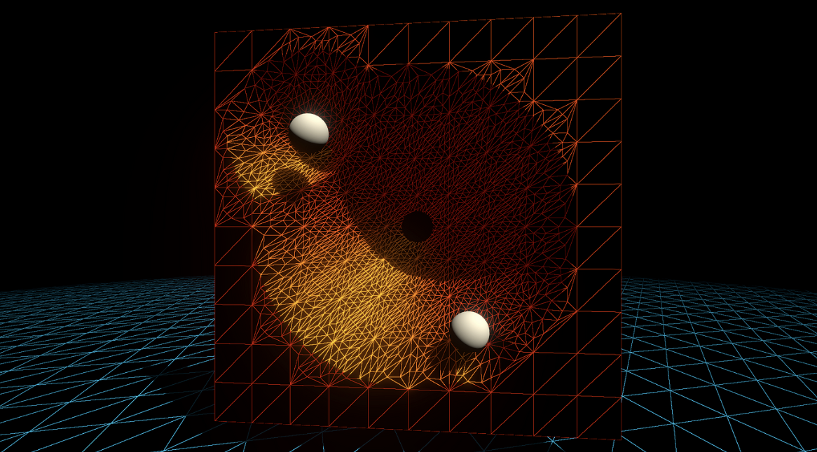
结合有符号距离场(Signed Distance Field, SDF)来控制曲面细分(Tessellation)因子,相当的酷炫。当然本节不涉及SDF的生成,假设能够直接通过现成的函数 CalculateSDFDistance 获取。
对于给定的Mesh,用 CalculateSDFDistance 计算出每个Patch中各个顶点到SDF表示的形状(例如球体)的距离。得到距离后再评估该Patch的细分需求,进行细分。
TessellationFactors PatchConstantFunction(
    InputPatch<TessellationControlPoint, 3> patch) {
    float multipliers[3];

    // 循环处理每个顶点
    [unroll] for (int i = 0; i < 3; i++) {
        // 计算每个顶点到SDF表面的距离
        float sdfDistance = CalculateSDFDistance(patch[i].positionWS);

        // 根据SDF距离调整细分因子
        if (sdfDistance < _TessellationDistanceThreshold) {
            multipliers[i] = lerp(_MinTessellationFactor, _MaxTessellationFactor, (1 - sdfDistance / _TessellationDistanceThreshold));
        } else {
            multipliers[i] = _MinTessellationFactor;
        }
    }

    // 计算最终的细分因子
    TessellationFactors f;
    f.Edge[0] = max(multipliers[0], multipliers[1]);
    f.Edge[1] = max(multipliers[1], multipliers[2]);
    f.Edge[2] = max(multipliers[2], multipliers[0]);
    f.Inside = (multipliers[0] + multipliers[1] + multipliers[2]) / 3;

    return f;
}
具体实现我也不会,先庄懂一下。

为一个Mesh添加细节最简单的方法是上各种高分辨率贴图。但是底大一级压死人,说的就是增加Mesh顶点的效果比增加贴图分辨率的效果要好。举个例子,法线贴图虽然可以改变每一个片元的法线方向,但是并不会改变几何外观。就算是128K的纹理也无法消除锯齿和pointy的边缘。

因此需要上曲面细分,然后偏移顶点。刚刚提到的所有曲面细分操作都是在Patch所在的平面上操作的。如果我们想要弯曲这些顶点,一个最简单的操作就是Phong细分。
首先附上原论文。https://perso.telecom-paristech.fr/boubek/papers/PhongTessellation/PhongTessellation.pdf
Phong着色应该很熟悉,是一种利用法向量线性差值得到平滑的着色的技术。Phong细分的灵感来自Phong着色,将Phong着色这一概念扩展到空间域。
Phong细分的核心思想是利用三角形每个角的顶点法线来影响细分过程中新顶点的位置,从而创造出曲面而非平面。
值得注意一下,这里很多教程会用triangle corner(三角形的角)来表示顶点,我觉得都差不多,本文还是用回顶点。
首先,在Domain函数内unity会给我们当前需要处理的新顶点的重心坐标。假设我们现在处理的是 (13,13,13) 。

Patch的每一个顶点都有法线。想象从每一个顶点发出一个切平面,垂直于各自的法向量。


然后将当前的顶点分别投影到这三个切平面上。

用数学语言描述。 P′=P−((P−V)⋅N)N
其中 :
得到三个 $P’$ 。


投影在三个切平面的三个点重新组成一个新的三角形,再用回当前顶点的重心坐标应用到新的三角形上,计算出新的点。

// Calculate Phong projection offset
float3 PhongProjectedPosition(float3 flatPositionWS, float3 cornerPositionWS, float3 normalWS) {
    return flatPositionWS - dot(flatPositionWS - cornerPositionWS, normalWS) * normalWS;
}

// Apply Phong smoothing
float3 CalculatePhongPosition(float3 bary, float3 p0PositionWS, float3 p0NormalWS,
    float3 p1PositionWS, float3 p1NormalWS, float3 p2PositionWS, float3 p2NormalWS) {
    float3 smoothedPositionWS =
        bary.x * PhongProjectedPosition(flatPositionWS, p0PositionWS, p0NormalWS) +
        bary.y * PhongProjectedPosition(flatPositionWS, p1PositionWS, p1NormalWS) +
        bary.z * PhongProjectedPosition(flatPositionWS, p2PositionWS, p2NormalWS);
    return smoothedPositionWS;
}

// The domain function runs once per vertex in the final, tessellated mesh
// Use it to reposition vertices and prepare for the fragment stage
[domain("tri")] // Signal we're inputting triangles
Interpolators Domain(
    TessellationFactors factors, // The output of the patch constant function
    OutputPatch<TessellationControlPoint, 3> patch, // The Input triangle
    float3 barycentricCoordinates : SV_DomainLocation) { // The barycentric coordinates of the vertex on the triangle

    Interpolators output;
    ...
    float3 positionWS = CalculatePhongPosition(barycentricCoordinates,
      patch[0].positionWS, patch[0].normalWS,
      patch[1].positionWS, patch[1].normalWS,
      patch[2].positionWS, patch[2].normalWS);
    float3 normalWS = BARYCENTRIC_INTERPOLATE(normalWS);
    float3 tangentWS = BARYCENTRIC_INTERPOLATE(tangentWS.xyz);
    ...
    output.positionCS = TransformWorldToHClip(positionWS);
    output.normalWS = normalWS;
    output.positionWS = positionWS;
    output.tangentWS = float4(tangentWS, patch[0].tangentWS.w);
    ...
}
注意这里需要添加法线向量,然后写进Vertex和Domain。再写一个计算算 $P’$ 重心坐标的函数。
struct Attributes {
    ...
    float4 tangentOS : TANGENT;
};
struct TessellationControlPoint {
    ...
    float4 tangentWS : TANGENT;
};
struct Interpolators {
    ...
    float4 tangentWS : TANGENT;
};
TessellationControlPoint Vertex(Attributes input) {
    TessellationControlPoint output;
    ...
    // .....最后一个是符号系数
    output.tangentWS = float4(normalInputs.tangentWS, input.tangentOS.w); // tangent.w containts bitangent multiplier
}
// Barycentric interpolation as a function
float3 BarycentricInterpolate(float3 bary, float3 a, float3 b, float3 c) {
    return bary.x * a + bary.y * b + bary.z * c;
}
在Phong细分原论文中,还加入了一个 α 因子,用于控制弯曲的程度。原文作者推荐将这个数值全局地设置为四分之三,这样的视觉效果最好。将含有 α 因子的算法展开后可以得到二次贝塞尔曲线,虽然不能提供拐点但是实际开发中已经足够使用。

首先看看原论文的公式。

本质上就是控制插值的程度,定量分析一下就知道,当 α=0 的时候,所有顶点都在原来的平面上,也就相当于没有任何位移。当 α=1 的时候,新的顶点完全依赖于Phong细分弯曲顶点。当然,你也可以尝试小于零或者大于一的数值,效果也是比较有趣的。~~看不懂原文的数学公式没关系,我反手直接上一个lerp,主打一个胡乱插值。~~
// Apply Phong smoothing
float3 CalculatePhongPosition(float3 bary, float smoothing, float3 p0PositionWS, float3 p0NormalWS,
    float3 p1PositionWS, float3 p1NormalWS, float3 p2PositionWS, float3 p2NormalWS) {
    float3 flatPositionWS = BarycentricInterpolate(bary, p0PositionWS, p1PositionWS, p2PositionWS);
    float3 smoothedPositionWS =
        bary.x * PhongProjectedPosition(flatPositionWS, p0PositionWS, p0NormalWS) +
        bary.y * PhongProjectedPosition(flatPositionWS, p1PositionWS, p1NormalWS) +
        bary.z * PhongProjectedPosition(flatPositionWS, p2PositionWS, p2NormalWS);
    return lerp(flatPositionWS, smoothedPositionWS, smoothing);
}
别忘了暴露在材质面板中。
// .shader
_TessellationSmoothing("_TessellationSmoothing", Range(0,1)) = 0.5

// .hlsl
float _TessellationSmoothing;


Interpolators Domain( .... ) {
    ...
    float smoothing = _TessellationSmoothing;
    float3 positionWS = CalculatePhongPosition(barycentricCoordinates, smoothing,
      patch[0].positionWS, patch[0].normalWS,
      patch[1].positionWS, patch[1].normalWS,
      patch[2].positionWS, patch[2].normalWS);
    ...
}
需要特别注意的是,有些模型需要一些修饰。如果模型的边缘非常锐利,那么就说明这个顶点的法线和所在面的法线几乎平行。在Phong Tessellation中,这会导致顶点在切平面上的投影非常接近于原始的顶点位置,从而使得细分的影响减少。
为了解决这个问题,可以在建模软件中进行所谓的“添加环边”(adding loop edges)或“环切割”(loop cut),以添加更多的几何细节。在原模型的边缘附近插入额外的边缘环,从而增加细分密度。具体操作这里就不展开了。
总的来说,Phong细分的效果和性能都相对不错。但是如果希望得到更高品质的平滑效果,可以考虑 PN triangles。该技术基于贝塞尔曲线弯曲三角形。
首先附上原论文。http://alex.vlachos.com/graphics/CurvedPNTriangles.pdf
PN Triangles不需要邻近三角形的信息,并且成本较低。PN Triangles算法只需要Patch里的三个顶点的位置和法线信息。剩下的数据都可以通过计算得到。注意,所有数据都在重心坐标。
在PN算法中,需要先计算出10个控制点用于曲面细分,如下图所示。三个三角形的顶点,一个重心,还有三对边上的控制点组成所有控制点。计算得到的贝塞尔曲线控制点,会传给Domain。由于每个三角形Patch的控制点都是一致的,因此计算控制点的步骤放在Patch Constant Function非常合适。

论文中的计算方式如下:
$$
\begin{aligned}
b_{300} & =P_1 \
b_{030} & =P_2 \
b_{003} & =P_3 \
w_{i j} & =\left(P_j-P_i\right) \cdot N_i \in \mathbf{R} \quad \text { here ‘ } \cdot \text { ‘ is the scalar product, } \
b_{210} & =\left(2 P_1+P_2-w_{12} N_1\right) / 3 \
b_{120} & =\left(2 P_2+P_1-w_{21} N_2\right) / 3 \
b_{021} & =\left(2 P_2+P_3-w_{23} N_2\right) / 3 \
b_{012} & =\left(2 P_3+P_2-w_{32} N_3\right) / 3 \
b_{102} & =\left(2 P_3+P_1-w_{31} N_3\right) / 3, \
b_{201} & =\left(2 P_1+P_3-w_{13} N_1\right) / 3, \
E & =\left(b_{210}+b_{120}+b_{021}+b_{012}+b_{102}+b_{201}\right) / 6 \
V & =\left(P_1+P_2+P_3\right) / 3, \
b_{111} & =E+(E-V) / 2 .
\end{aligned}
$$
公式中的 $w_{i j}$ 每条边都会计算两次,因此一共会计算6次。比如 $w_{1 2}$ 的意义就是,$P_1$ 到 $P_2$ 的向量在 $P_1$ 法线方向上的投影长度。再乘上对应的法线方向就表示 $w$ 为长度的投影向量。
还是计算靠近 $P_1$ 的因子为例,当前位置点的权重应该较大,乘上一个 $2$ 使得计算出来的控制点更加靠近当前的顶点。减去投影向量的原因是为了修正因 $P_2$ 位置不在 $P_1$ 法线定义的平面上而导致的误差。让三角形平面更加吻合,减少扭曲效果。最后再除3,为了标准化。
接着计算平均贝塞尔控制点 $E$ ,表示六个控制点的平均位置。这个平均位置代表了边界控制点的集中趋势。然后算一下三角形顶点的平均位置。然后求出这两个平均位置的中点位置,加到贝塞尔平均控制点。这就是最终要求的第十个参数了。
总结一下,前三个是三角形的顶点位置(因此不用写在结构体里面),有六个是通过权重计算,最后一个是集合前面计算的平均起来。代码书写非常简单。
struct TessellationFactors {
    float edge[3] : SV_TessFactor;
    float inside : SV_InsideTessFactor;
    float3 bezierPoints[7] : BEZIERPOS;
};

//Bezier control point calculations
float3 CalculateBezierControlPoint(float3 p0PositionWS, float3 aNormalWS, float3 p1PositionWS, float3 bNormalWS) {
    float w = dot(p1PositionWS - p0PositionWS, aNormalWS);
    return (p0PositionWS * 2 + p1PositionWS - w * aNormalWS) / 3.0;
}

void CalculateBezierControlPoints(inout float3 bezierPoints[7],
    float3 p0PositionWS, float3 p0NormalWS, float3 p1PositionWS, float3 p1NormalWS, float3 p2PositionWS, float3 p2NormalWS) {
    bezierPoints[0] = CalculateBezierControlPoint(p0PositionWS, p0NormalWS, p1PositionWS, p1NormalWS);
    bezierPoints[1] = CalculateBezierControlPoint(p1PositionWS, p1NormalWS, p0PositionWS, p0NormalWS);
    bezierPoints[2] = CalculateBezierControlPoint(p1PositionWS, p1NormalWS, p2PositionWS, p2NormalWS);
    bezierPoints[3] = CalculateBezierControlPoint(p2PositionWS, p2NormalWS, p1PositionWS, p1NormalWS);
    bezierPoints[4] = CalculateBezierControlPoint(p2PositionWS, p2NormalWS, p0PositionWS, p0NormalWS);
    bezierPoints[5] = CalculateBezierControlPoint(p0PositionWS, p0NormalWS, p2PositionWS, p2NormalWS);
    float3 avgBezier = 0;
    [unroll] for (int i = 0; i < 6; i++) {
        avgBezier += bezierPoints[i];
    }
    avgBezier /= 6.0;
    float3 avgControl = (p0PositionWS + p1PositionWS + p2PositionWS) / 3.0;
    bezierPoints[6] = avgBezier + (avgBezier - avgControl) / 2.0;
}

// The patch constant function runs once per triangle, or "patch"
// It runs in parallel to the hull function
TessellationFactors PatchConstantFunction(
    InputPatch<TessellationControlPoint, 3> patch) {
    ...
    TessellationFactors f = (TessellationFactors)0;
    // Check if this patch should be culled (it is out of view)
    if (ShouldClipPatch(...)) {
        ...
    } else {
        ...
        CalculateBezierControlPoints(f.bezierPoints, patch[0].positionWS, patch[0].normalWS,
          patch[1].positionWS, patch[1].normalWS, patch[2].positionWS, patch[2].normalWS);
    }
    return f;
}
接着在domain函数中,使用Hull Function输出的十个因子。根据论文给出的公式,计算出最终的立方贝塞尔曲面坐标。然后再插值一下,暴露到材质面板上。
$$
\begin{aligned}
& b: \quad R^2 \mapsto R^3, \quad \text { for } w=1-u-v, \quad u, v, w \geq 0 \
& b(u, v)= \sum_{i+j+k=3} b_{i j k} \frac{3!}{i!j!k!} u^i v^j w^k \
&= b_{300} w^3+b_{030} u^3+b_{003} v^3 \
&+b_{210} 3 w^2 u+b_{120} 3 w u^2+b_{201} 3 w^2 v \
&+b_{021} 3 u^2 v+b_{102} 3 w v^2+b_{012} 3 u v^2 \
&+b_{111} 6 w u v .
\end{aligned}
$$
// Barycentric interpolation as a function
float3 BarycentricInterpolate(float3 bary, float3 a, float3 b, float3 c) {
    return bary.x * a + bary.y * b + bary.z * c;
}

float3 CalculateBezierPosition(float3 bary, float smoothing, float3 bezierPoints[7],
    float3 p0PositionWS, float3 p1PositionWS, float3 p2PositionWS) {
    float3 flatPositionWS = BarycentricInterpolate(bary, p0PositionWS, p1PositionWS, p2PositionWS);
    float3 smoothedPositionWS =
        p0PositionWS * (bary.x * bary.x * bary.x) +
        p1PositionWS * (bary.y * bary.y * bary.y) +
        p2PositionWS * (bary.z * bary.z * bary.z) +
        bezierPoints[0] * (3 * bary.x * bary.x * bary.y) +
        bezierPoints[1] * (3 * bary.y * bary.y * bary.x) +
        bezierPoints[2] * (3 * bary.y * bary.y * bary.z) +
        bezierPoints[3] * (3 * bary.z * bary.z * bary.y) +
        bezierPoints[4] * (3 * bary.z * bary.z * bary.x) +
        bezierPoints[5] * (3 * bary.x * bary.x * bary.z) +
        bezierPoints[6] * (6 * bary.x * bary.y * bary.z);
    return lerp(flatPositionWS, smoothedPositionWS, smoothing);
}

// The domain function runs once per vertex in the final, tessellated mesh
// Use it to reposition vertices and prepare for the fragment stage
[domain("tri")] // Signal we're inputting triangles
Interpolators Domain(
    TessellationFactors factors, // The output of the patch constant function
    OutputPatch<TessellationControlPoint, 3> patch, // The Input triangle
    float3 barycentricCoordinates : SV_DomainLocation) { // The barycentric coordinates of the vertex on the triangle

    Interpolators output;
    ...
    // Calculate tessellation smoothing multipler
    float smoothing = _TessellationSmoothing;
#ifdef _TESSELLATION_SMOOTHING_VCOLORS
    smoothing *= BARYCENTRIC_INTERPOLATE(color.r); // Multiply by the vertex's red channel
#endif

    float3 positionWS = CalculateBezierPosition(barycentricCoordinates,
      smoothing, factors.bezierPoints,
      patch[0].positionWS, patch[1].positionWS, patch[2].positionWS);
    float3 normalWS = BARYCENTRIC_INTERPOLATE(normalWS);
    float3 tangentWS = BARYCENTRIC_INTERPOLATE(tangentWS.xyz);
    ...
}
对比效果,关闭与开启PN triangles。
传统的PN triangles只改变了顶点的位置信息,我们可以再结合顶点的法线信息,输出动态变化的法线信息,提供更好的光线反射效果。
在原本的的算法中,法线的变化是非常离散的。如下图(上)所示,利用原本三角形的两个顶点提供的法线也许不能很好的表现原本曲面的法线变化。我们想要达到下图(下)的效果,因此需要利用二次插值得到单个Patch中可能的曲面变化。
由于曲面是三次贝塞尔面,所以法线应该是二次贝塞尔曲面插值。因此需要额外的三个法线控制点。TheTus的文章已经讲得比较清晰了,详细的数学原理请移步Ref10.链接。

下面简单介绍一下如何获取细分的法线方向。
首先获取点AB的两个法线信息。然后求出他们的平均法向。

构造一个垂直于线段AB过中点的平面。

取刚刚平均法向对于该平面的反射向量。

每条边都算一下,算三个。

struct TessellationFactors {
    float edge[3] : SV_TessFactor;
    float inside : SV_InsideTessFactor;
    float3 bezierPoints[10] : BEZIERPOS;
};

float3 CalculateBezierControlNormal(float3 p0PositionWS, float3 aNormalWS, float3 p1PositionWS, float3 bNormalWS) {
    float3 d = p1PositionWS - p0PositionWS;
    float v = 2 * dot(d, aNormalWS + bNormalWS) / dot(d, d);
    return normalize(aNormalWS + bNormalWS - v * d);
}

void CalculateBezierNormalPoints(inout float3 bezierPoints[10],
    float3 p0PositionWS, float3 p0NormalWS, float3 p1PositionWS, float3 p1NormalWS, float3 p2PositionWS, float3 p2NormalWS) {
    bezierPoints[7] = CalculateBezierControlNormal(p0PositionWS, p0NormalWS, p1PositionWS, p1NormalWS);
    bezierPoints[8] = CalculateBezierControlNormal(p1PositionWS, p1NormalWS, p2PositionWS, p2NormalWS);
    bezierPoints[9] = CalculateBezierControlNormal(p2PositionWS, p2NormalWS, p0PositionWS, p0NormalWS);
}

// The patch constant function runs once per triangle, or "patch"
// It runs in parallel to the hull function
TessellationFactors PatchConstantFunction(
    InputPatch<TessellationControlPoint, 3> patch) {
    ...
    TessellationFactors f = (TessellationFactors)0;
    // Check if this patch should be culled (it is out of view)
    if (ShouldClipPatch(...)) {
        ..
    } else {
        ...
        CalculateBezierControlPoints(f.bezierPoints,
          patch[0].positionWS, patch[0].normalWS, patch[1].positionWS,
          patch[1].normalWS, patch[2].positionWS, patch[2].normalWS);
        CalculateBezierNormalPoints(f.bezierPoints,
          patch[0].positionWS, patch[0].normalWS, patch[1].positionWS,
          patch[1].normalWS, patch[2].positionWS, patch[2].normalWS);
    }
    return f;
}
并且需要注意,所有插值得到的法线向量都需要标准化。
float3 CalculateBezierNormal(float3 bary, float3 bezierPoints[10],
    float3 p0NormalWS, float3 p1NormalWS, float3 p2NormalWS) {
    return p0NormalWS * (bary.x * bary.x) +
        p1NormalWS * (bary.y * bary.y) +
        p2NormalWS * (bary.z * bary.z) +
        bezierPoints[7] * (2 * bary.x * bary.y) +
        bezierPoints[8] * (2 * bary.y * bary.z) +
        bezierPoints[9] * (2 * bary.z * bary.x);
}

float3 CalculateBezierNormalWithSmoothFactor(float3 bary, float smoothing, float3 bezierPoints[10],
    float3 p0NormalWS, float3 p1NormalWS, float3 p2NormalWS) {
    float3 flatNormalWS = BarycentricInterpolate(bary, p0NormalWS, p1NormalWS, p2NormalWS);
    float3 smoothedNormalWS = CalculateBezierNormal(bary, bezierPoints, p0NormalWS, p1NormalWS, p2NormalWS);
    return normalize(lerp(flatNormalWS, smoothedNormalWS, smoothing));
}

// The domain function runs once per vertex in the final, tessellated mesh
// Use it to reposition vertices and prepare for the fragment stage
[domain("tri")] // Signal we're inputting triangles
Interpolators Domain(
    TessellationFactors factors, // The output of the patch constant function
    OutputPatch<TessellationControlPoint, 3> patch, // The Input triangle
    float3 barycentricCoordinates : SV_DomainLocation) { // The barycentric coordinates of the vertex on the triangle

    Interpolators output;
    ...
    // Calculate tessellation smoothing multipler
    float smoothing = _TessellationSmoothing;
    float3 positionWS = CalculateBezierPosition(barycentricCoordinates, smoothing, factors.bezierPoints, patch[0].positionWS, patch[1].positionWS, patch[2].positionWS);
    float3 normalWS = CalculateBezierNormalWithSmoothFactor(
        barycentricCoordinates, smoothing, factors.bezierPoints,
        patch[0].normalWS, patch[1].normalWS, patch[2].normalWS);
    float3 tangentWS = BARYCENTRIC_INTERPOLATE(tangentWS.xyz);
    ...
}
还有一个问题需要注意,当我们使用了插值得到的法线,与之一一对应的切线向量就不再与插值得到的法线向量正交。为了保持正交性,需要重新计算一个切线向量。
void CalculateBezierNormalAndTangent(
    float3 bary, float smoothing, float3 bezierPoints[10],
    float3 p0NormalWS, float3 p0TangentWS,
    float3 p1NormalWS, float3 p1TangentWS,
    float3 p2NormalWS, float3 p2TangentWS,
    out float3 normalWS, out float3 tangentWS) {

    float3 flatNormalWS = BarycentricInterpolate(bary, p0NormalWS, p1NormalWS, p2NormalWS);
    float3 smoothedNormalWS = CalculateBezierNormal(bary, bezierPoints, p0NormalWS, p1NormalWS, p2NormalWS);
    normalWS = normalize(lerp(flatNormalWS, smoothedNormalWS, smoothing));

    float3 flatTangentWS = BarycentricInterpolate(bary, p0TangentWS, p1TangentWS, p2TangentWS);
    float3 flatBitangentWS = cross(flatNormalWS, flatTangentWS);
    tangentWS = normalize(cross(flatBitangentWS, normalWS));
}

[domain("tri")] // Signal we're inputting triangles
Interpolators Domain(
    TessellationFactors factors, // The output of the patch constant function
    OutputPatch<TessellationControlPoint, 3> patch, // The Input triangle
    float3 barycentricCoordinates : SV_DomainLocation) { // The barycentric coordinates of the vertex on the triangle
    ...
    float3 normalWS, tangentWS;
    CalculateBezierNormalAndTangent(
        barycentricCoordinates, smoothing, factors.bezierPoints,
        patch[0].normalWS, patch[0].tangentWS.xyz,
        patch[1].normalWS, patch[1].tangentWS.xyz,
        patch[2].normalWS, patch[2].tangentWS.xyz,
        normalWS, tangentWS);
    ...
}

在京都的三天,大概也是我人生中最幸福的瞬間之一吧。
旅行而言,去哪裏不重要,重要的是和誰一起去。
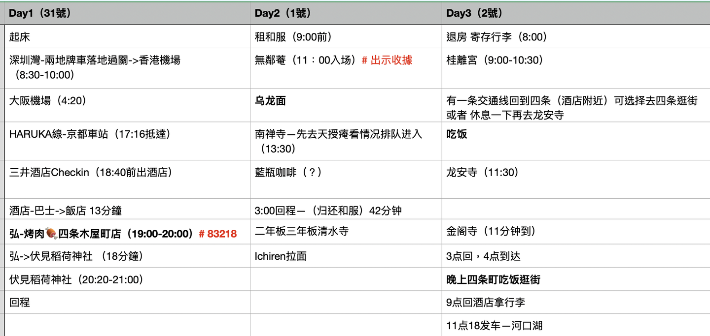
京都前十景點(按照個人喜好):


很多人說京都很無聊,但對於喜歡人文建築的我而言,這是我目前旅行過的城市中最滿意的一個。(在此之前,我最愛的旅行城市是愛丁堡。)
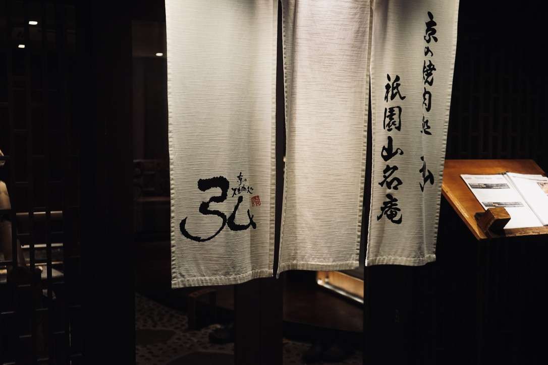
如果問我去日本旅行最需要注意什麼,我會告訴你,喫飯前一定要Reserve。雖然我在英國經歷過無數次即使餐廳空無一人但是服務員說如果你沒有預約就不能用餐的尷尬局面,但是還是在日本翻了一次車。原因是遲到了十分鐘,居酒屋的小哥便把我們拒之門外。
落地日本的第一天晚上,在經歷了被拒絕進入烤肉店喫飯的悲傷之後,我與友人馬不停蹄的坐地鐵+公交趕到伏見。具體怎麼個事呢?由於我與友人在酒店Checkin的時候耽誤了一些時間,導致抵達預訂的烤肉店的時間晚了十分鐘。於是心心念唸的烤肉店計劃就泡湯了,我與友人都難掩失望。好在第二天順利喫上了。
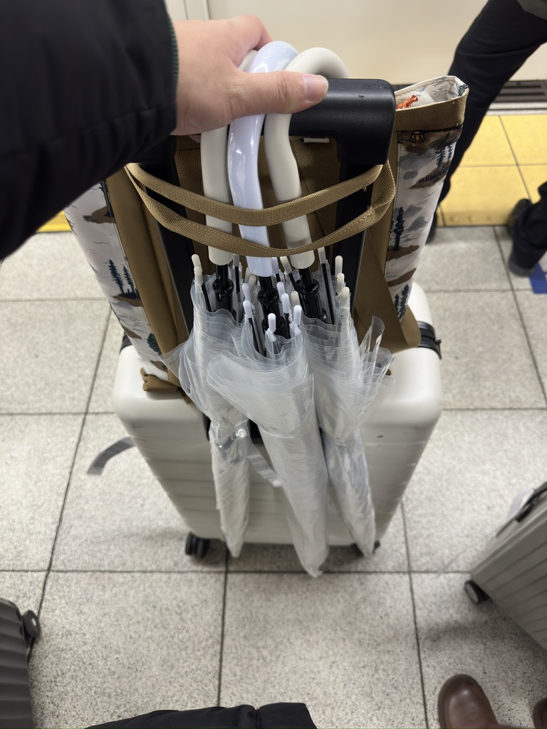
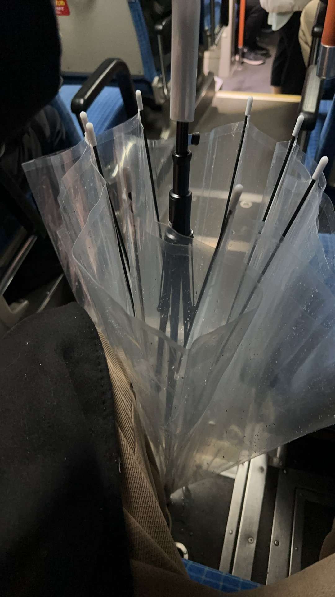
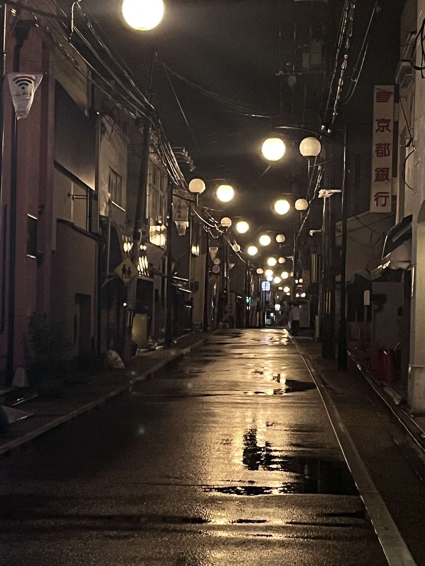
不巧的是,剛剛到了車站,就下起大雨。於是在便利店獲得了重要的裝備,透明傘。差一句題外話,日本的公交在停靠的時候,載人的一側會降低,挺不錯的。
我們這次是夜襲伏見稻荷大社,雖然比較陰間,但是景點的氛圍並沒有讓人感覺到恐怖。


一幕幕只有在動漫中才會出現的場景接踵而至,這種感覺真的很奇妙。


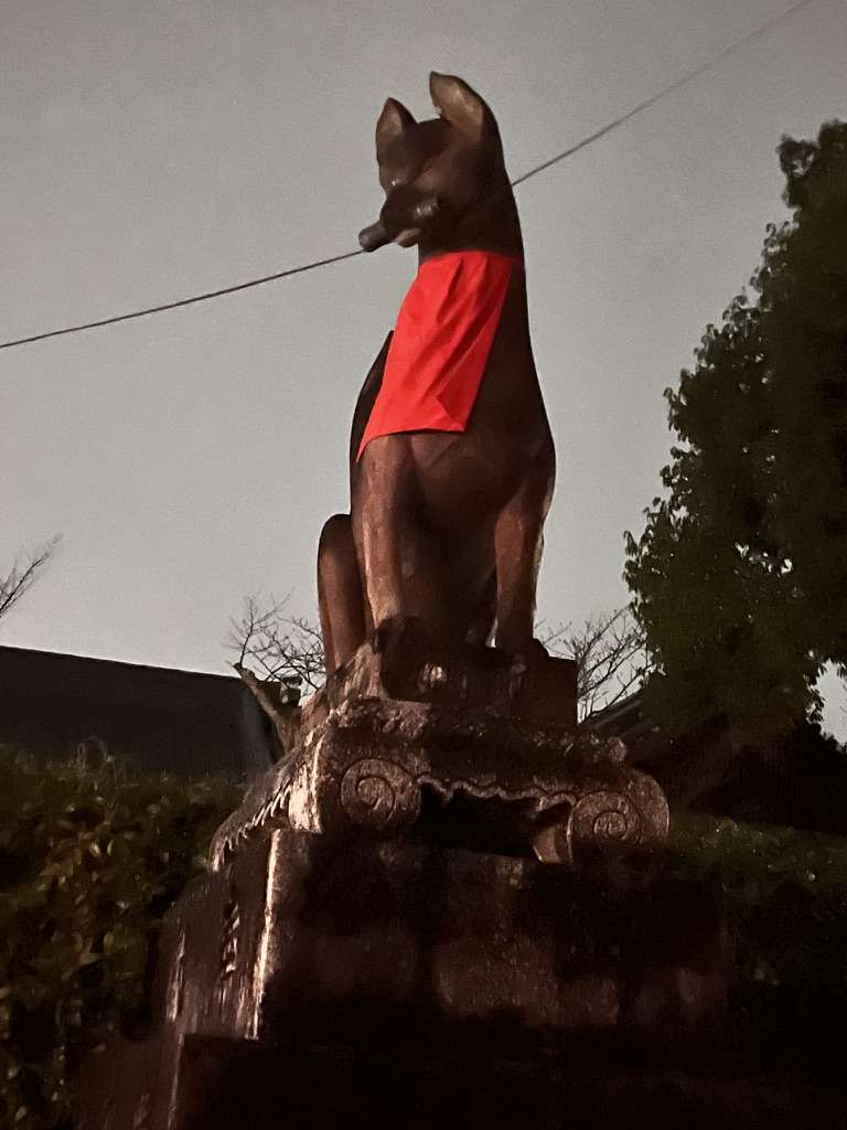
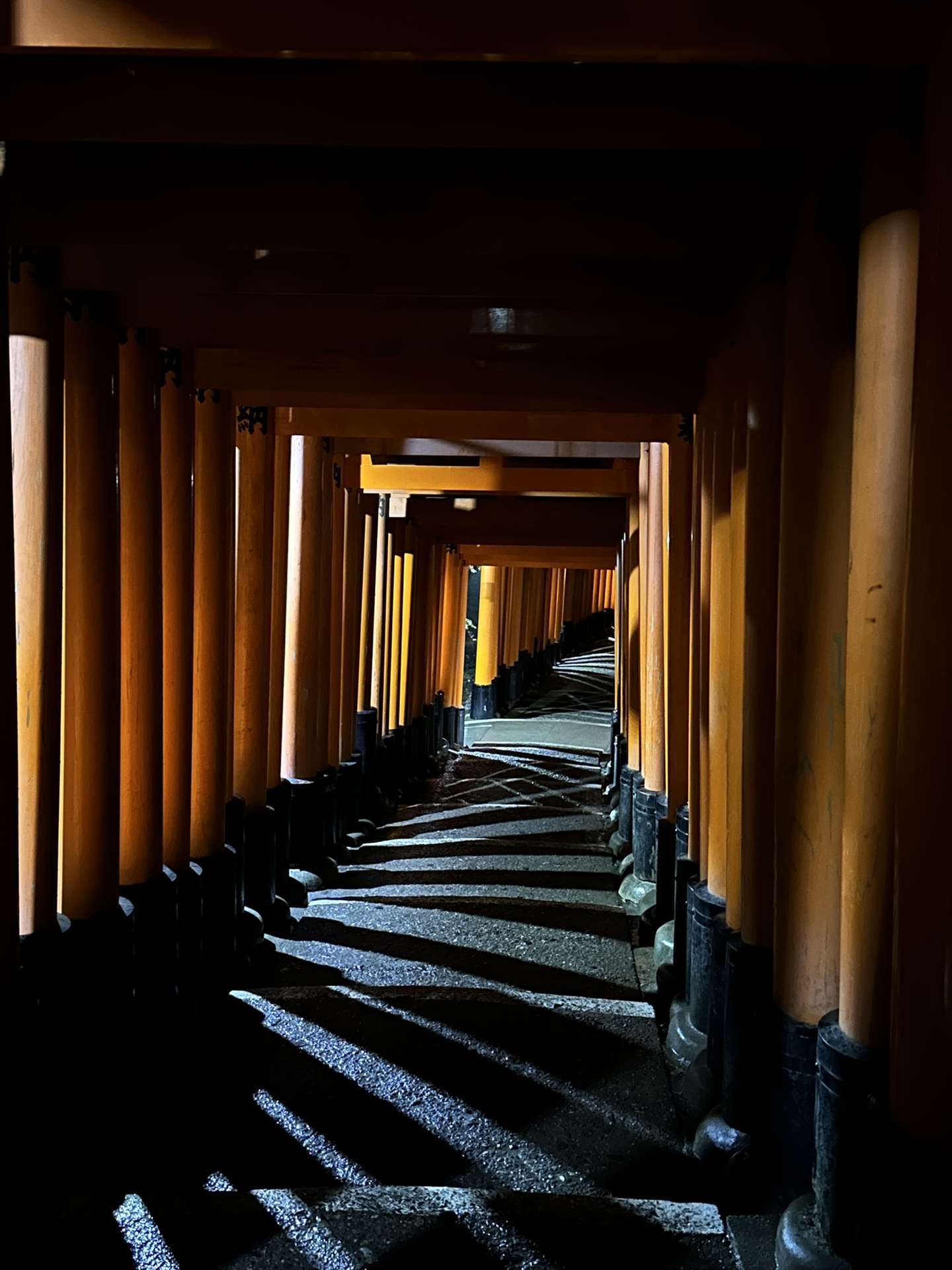
特別像日劇裏面男女主下班之後的空鏡頭。
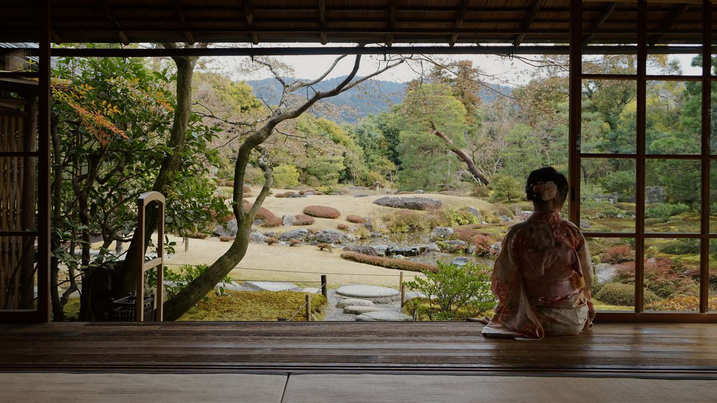
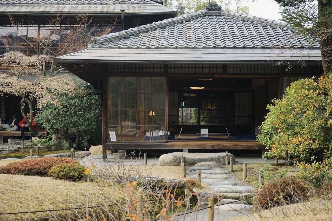
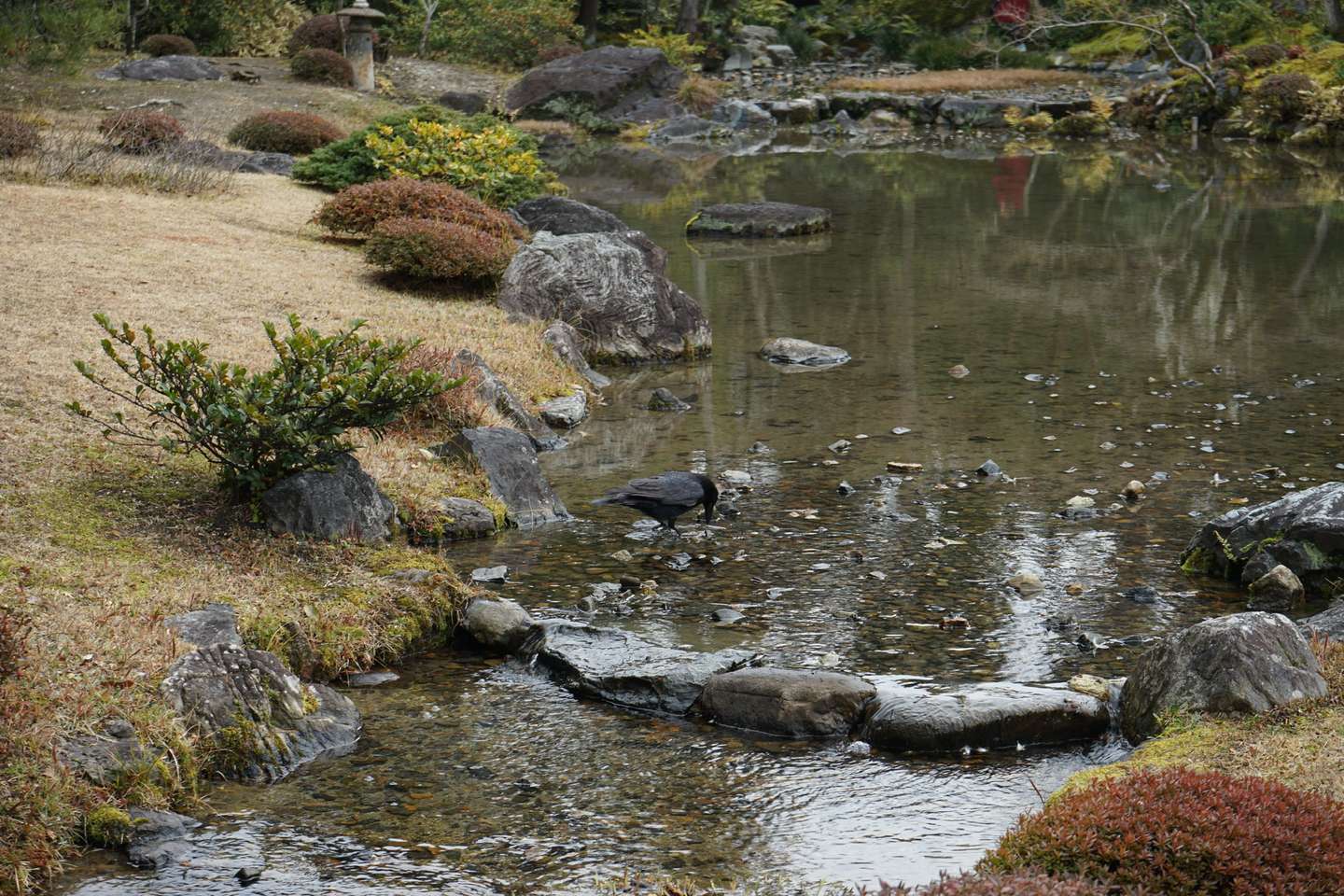
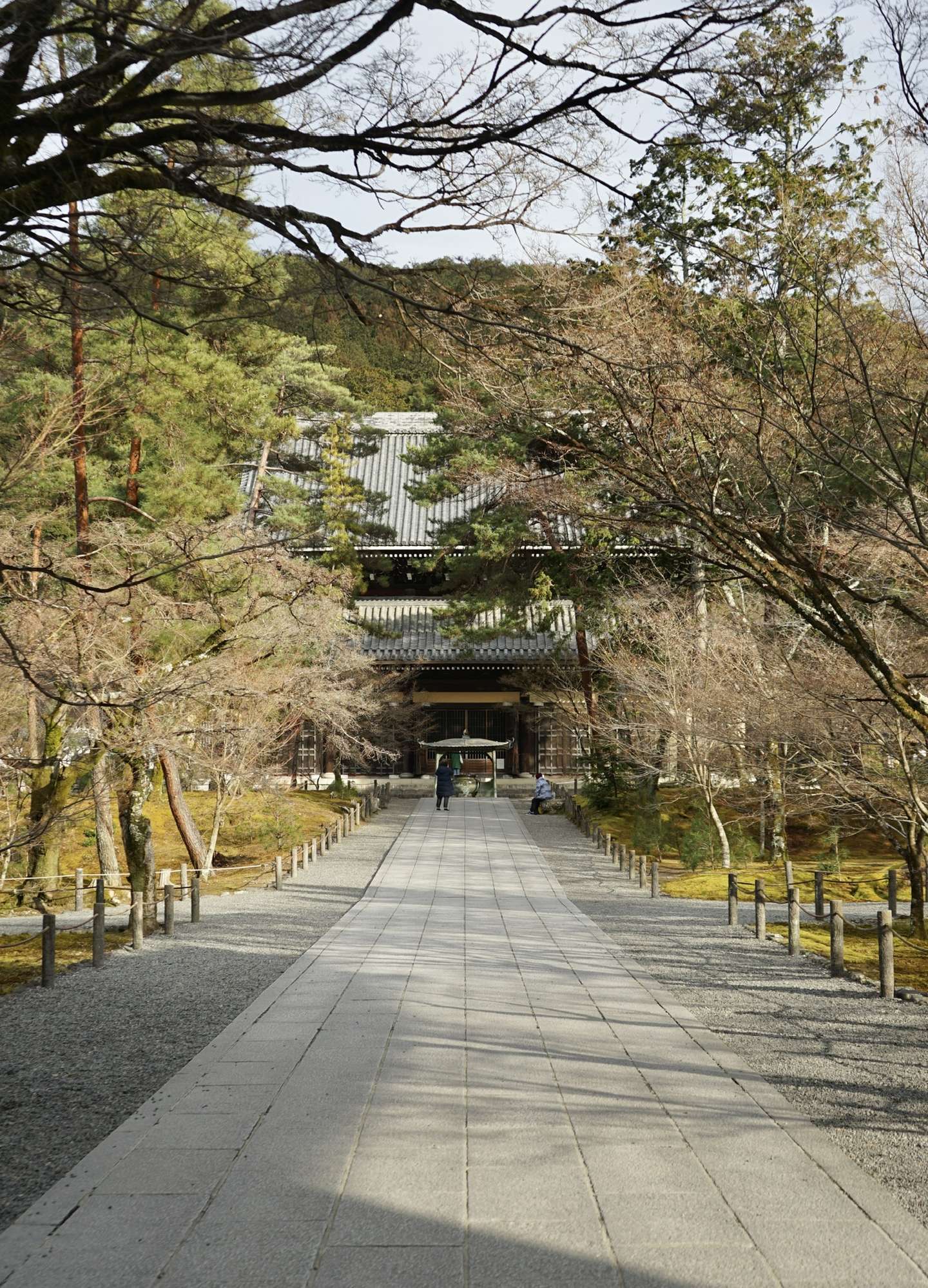
若要給景點排一個順序,我會毫不猶豫無鄰菴放在第一位。庭院以東山爲景,坐落於南禪寺一帶。

訂票的官方網站在下面,目前只支持VISA, MasterCard和JCB支付:
小而美的日式庭院,但實際上是明治時期西式的建築。主屋是簡潔的木製波形瓦建築,爲了能讓賓客充分觀賞庭園,建築的造型簡潔大方。
需要注意,人像攝影需要額外支付費用。或者是和管理員鬥智鬥勇。
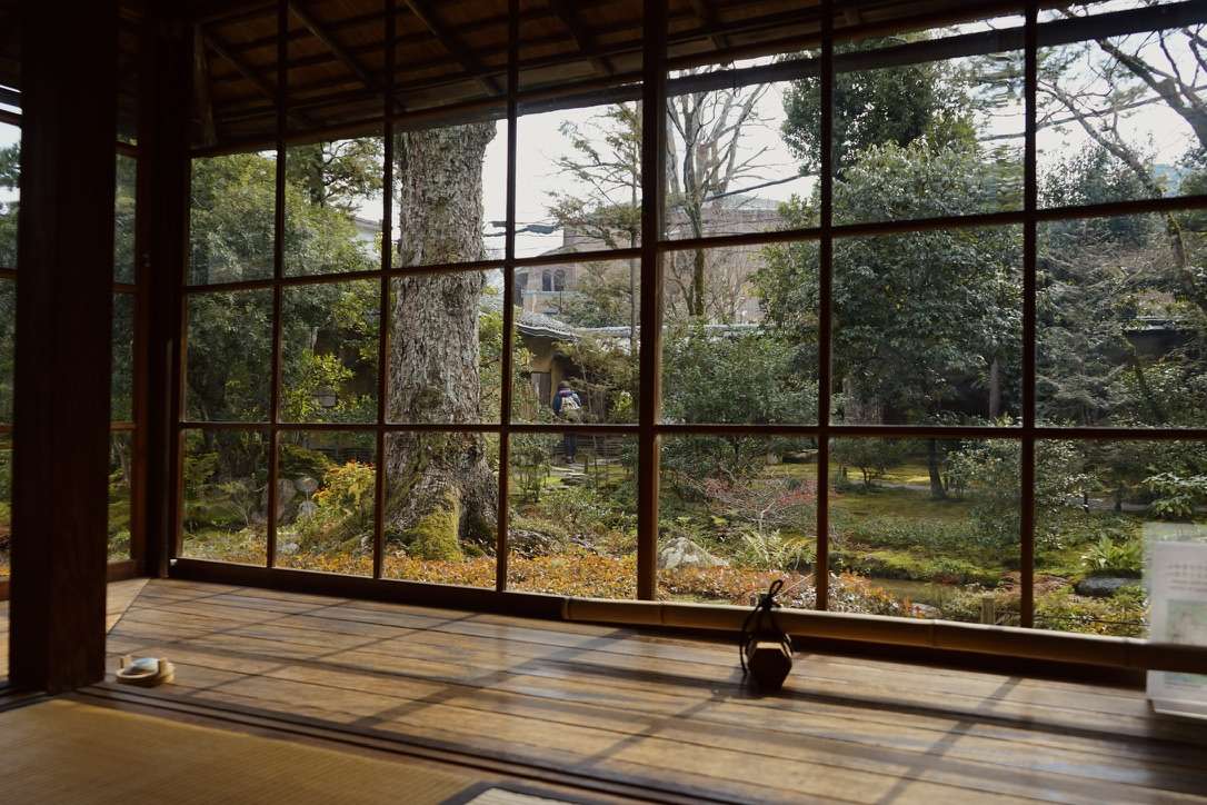
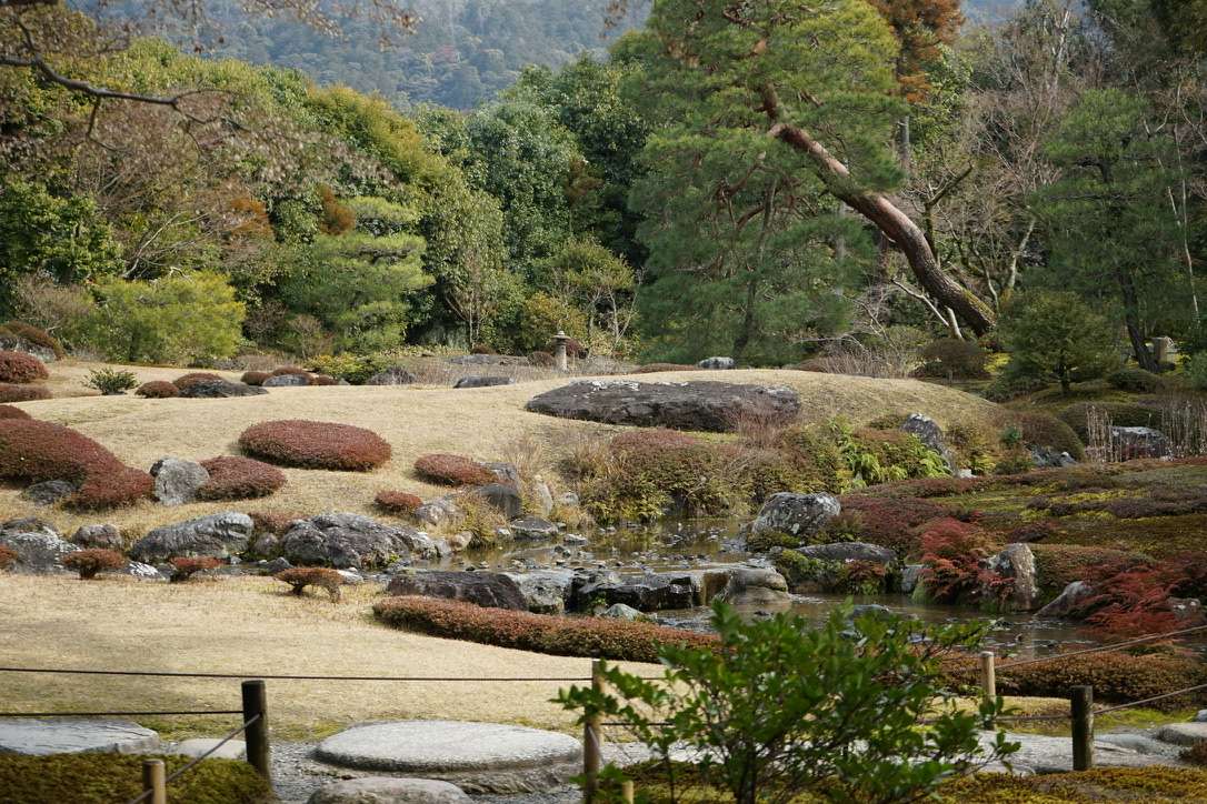
庭院擁有明亮開放的草坪空間以及引琵琶湖疏水之水而建的輕快地流水等景觀。
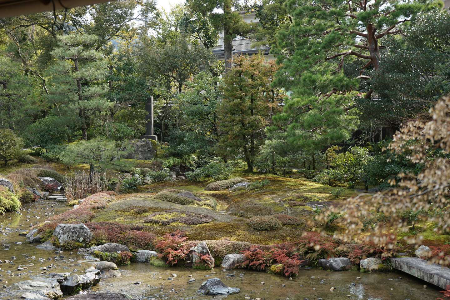
庭院的流水設計也是繼承自設計者山縣有朋的喜愛。
出了庭院,門口就是一家老奶奶經營的飯店。隔壁桌的婆孫倆聽到店裏正在播“音樂之聲”的BGM,手舞足蹈的跟着唱,特別治癒。

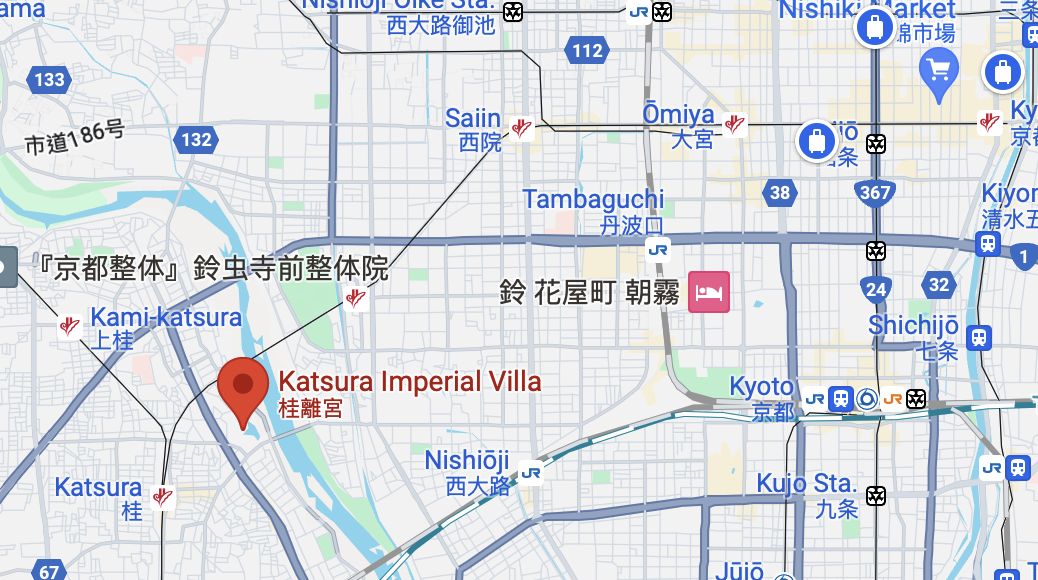
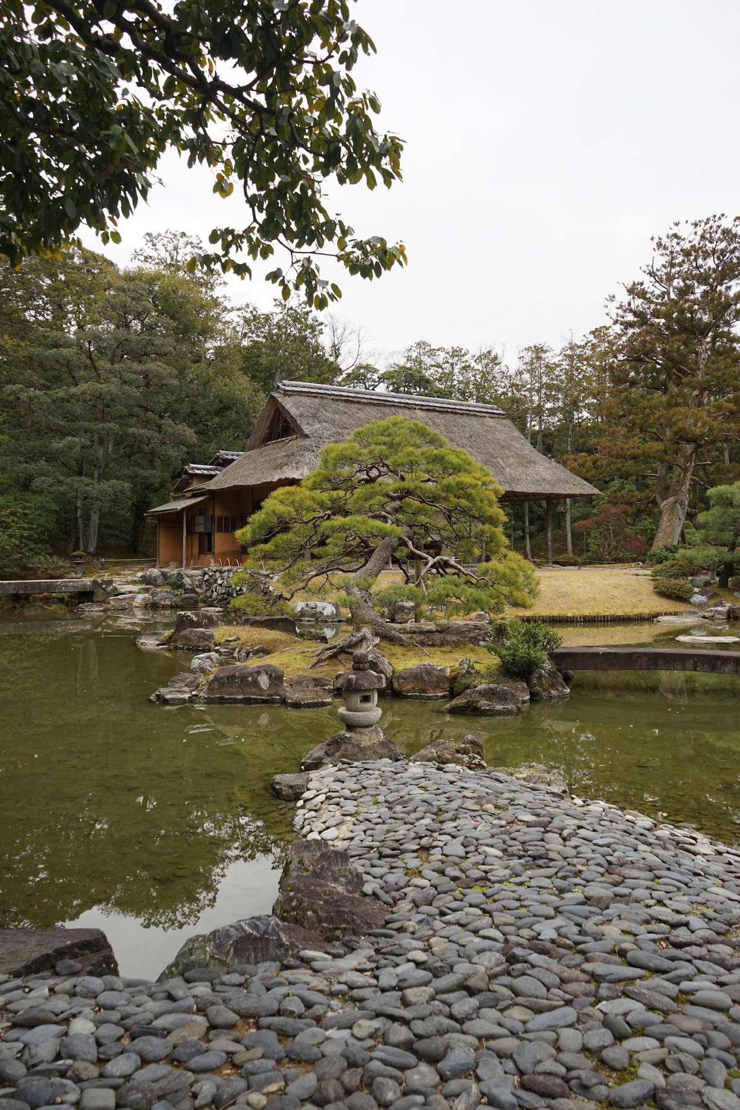
桂離宮的位置比較尷尬,位於京都的西南側。這邊的一個特點就是:遊客少且安靜。
這個景點是一位建築相關的教授推薦我們來的,喜歡景觀的朋友一定不要錯過。
雖然我不是景觀專業,但是我也可以切身感受到什麼是“自然中見人工”,什麼是“一步一景”。
並且很關鍵的一點是,你永遠看不到庭院的全貌,這是一種很獨特的體驗。

有人說這是最美的日本園林,我不會否認。
庭院只有日語嚮導,但幾乎所有遊客都不是日本人,所有人都佩戴着翻譯器,挺滑稽的。

庭院內外都散發着寧靜的氛圍。

庭院是線性設計的。每走一步就會得到完全不同的景色,特別像遊戲關卡設計。
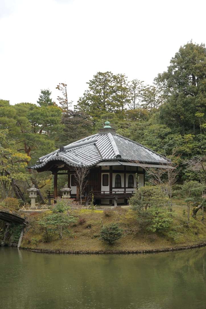
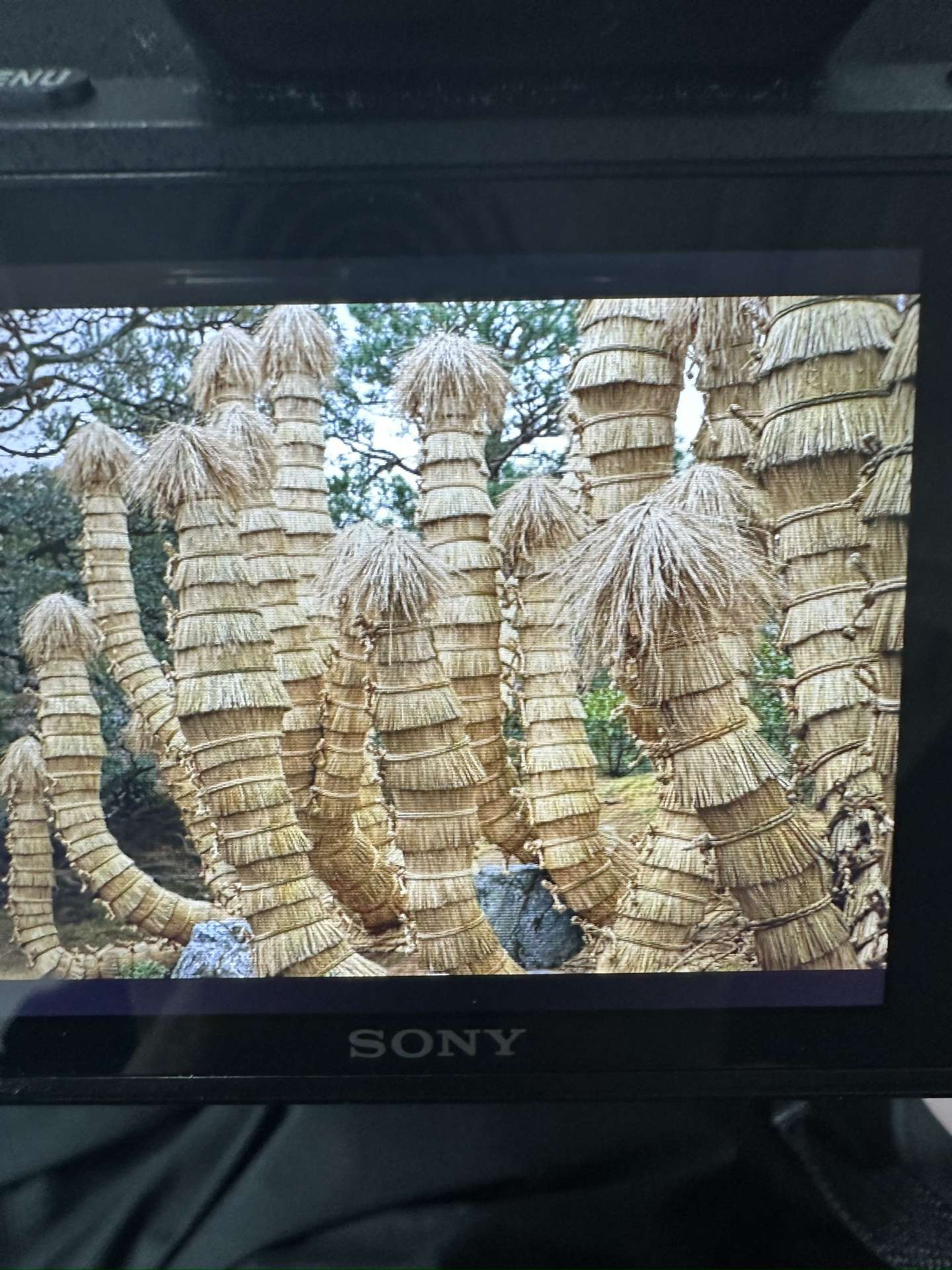
有很多座橋,嚮導特意提醒我們,不要在橋上拍照。
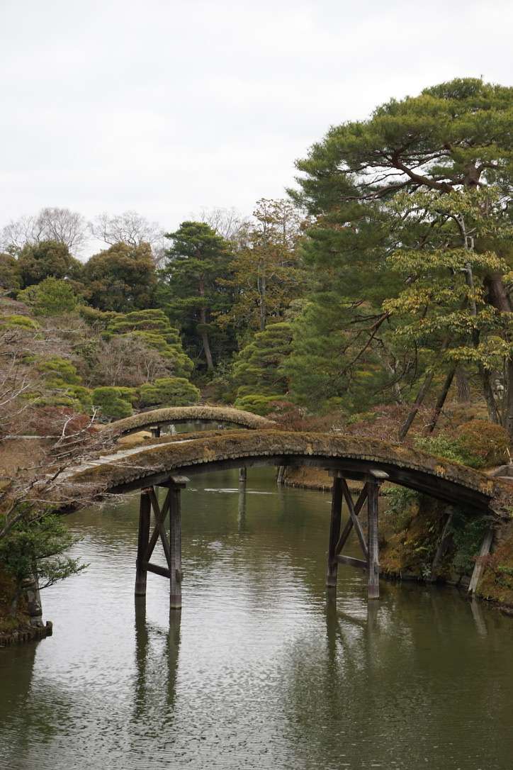
有朋友知道這是什麼嗎?
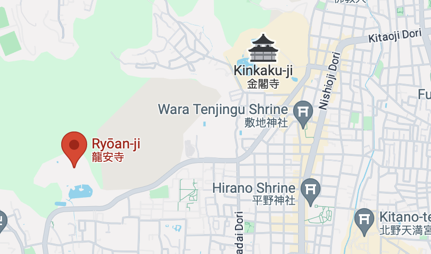
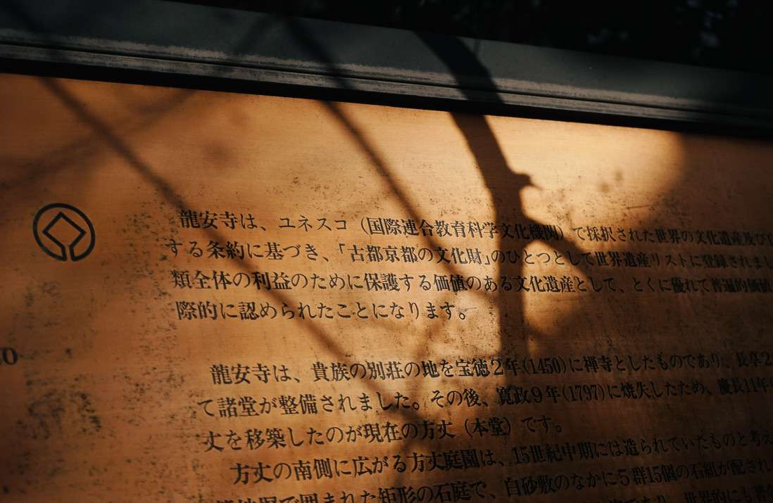
本次京都之旅最爲期待的幾個景點之一,龍安寺,在金閣寺的旁邊。這兩個景點是緊挨着的,通勤可以選擇坐公交,也可以像我一樣徒步。
日本的枯山水確實給我一種枯寂而玄妙之感。其中最有名的便是龍安寺的枯山水。
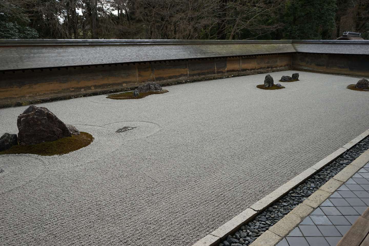
說實話,參觀完龍安寺之後,我是比較失望的。“怎麼就這?!”
就是說,龍安寺的枯山水庭院非常小,上面照片幾乎就是90%了。
失望地走出龍安寺之後,我遇到了一對美國老夫婦,身邊是一位英語嚮導。我與友人便不要臉地跟在他們身後,於是看到了下面的景色。


想必大家也感受過三島筆中金閣寺的美。但當我親眼目睹那金色的輝光時,還是不由得被震撼到。

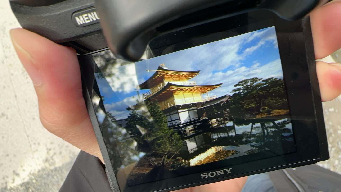
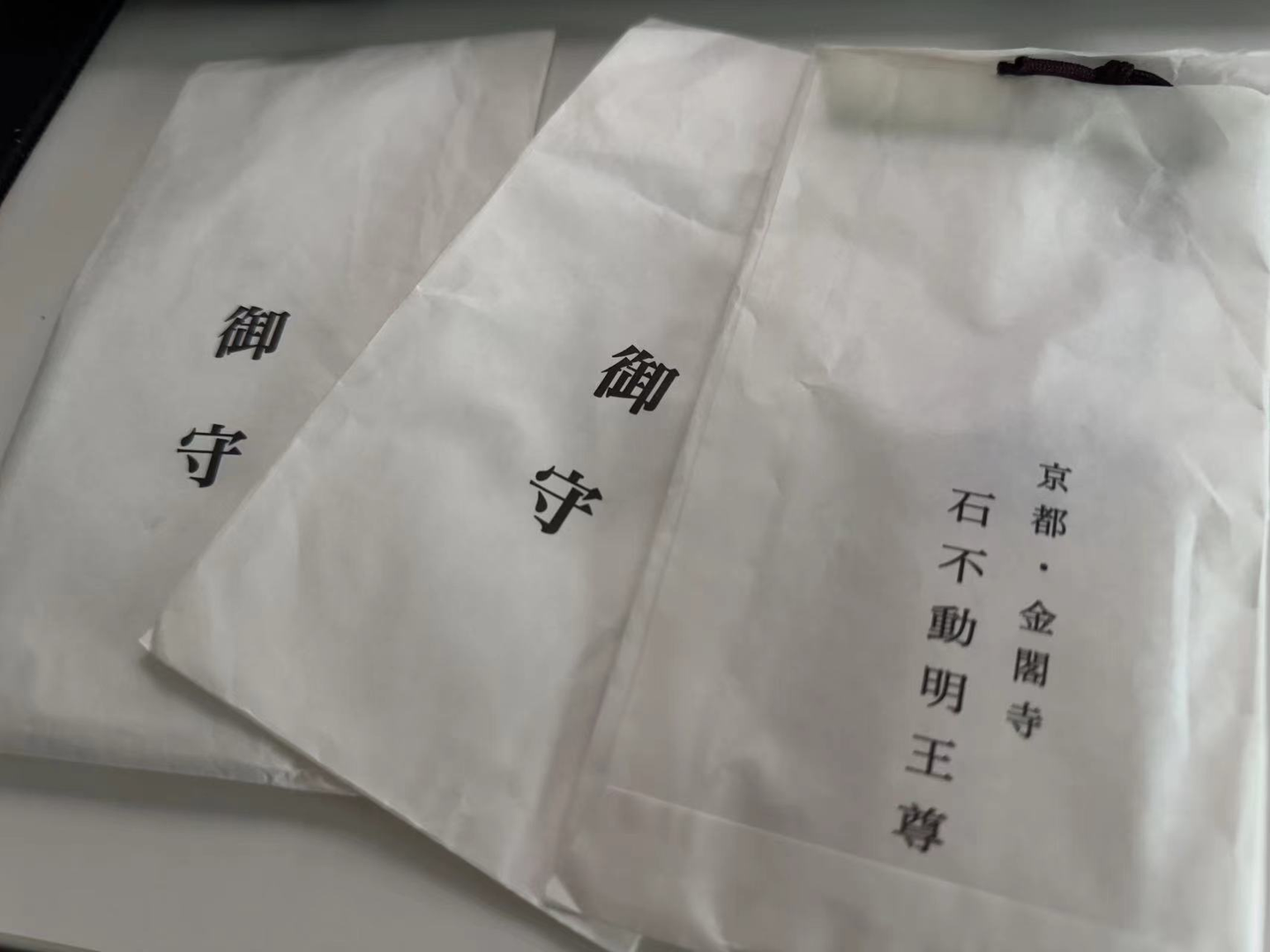
在金閣寺旁邊買了幾個祈求好運的御守。


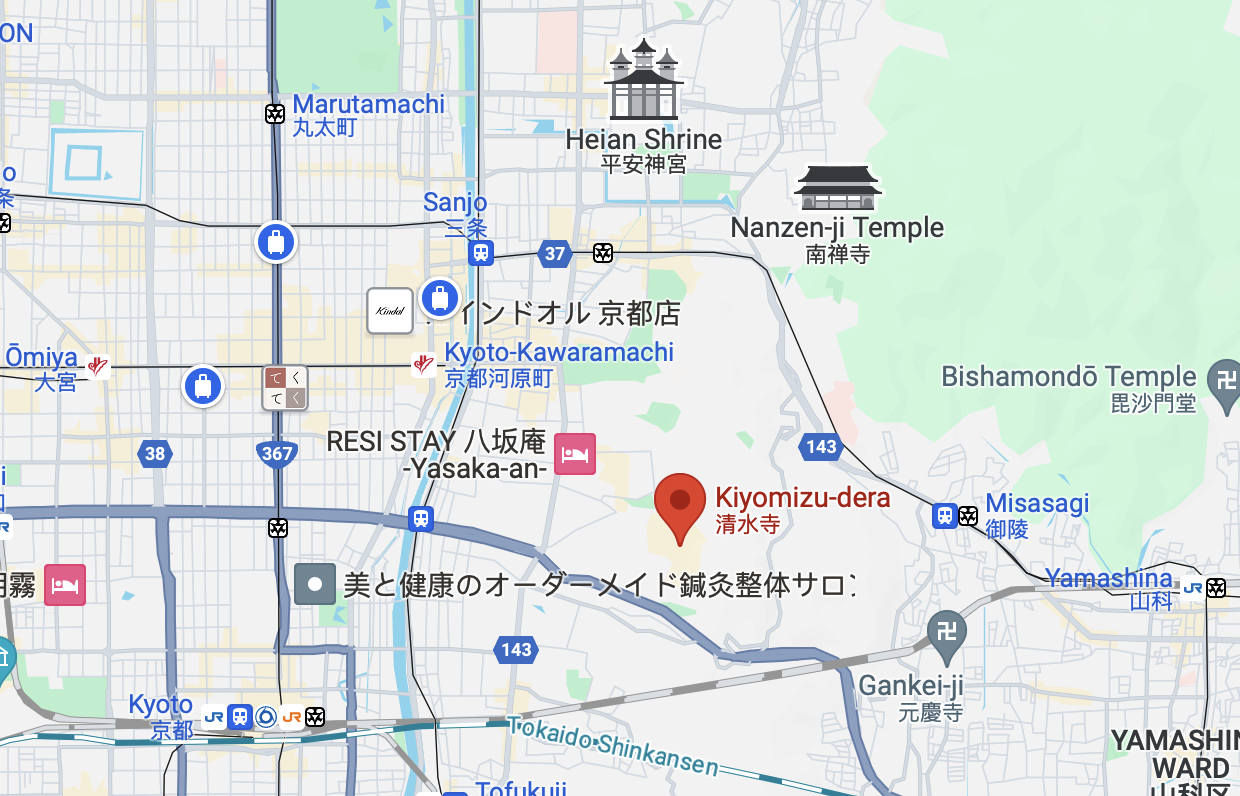
來京都,絕大多數人都會去的一個景點。可以順着二年坂/三年坂一路走。
這一邊真的好多人。


友人說我這張照片修得太過了,太像動漫了。實際上這是原圖。

當天色漸漸暗淡下來,我看到了動漫一般的場景,有一種莫名的感動。


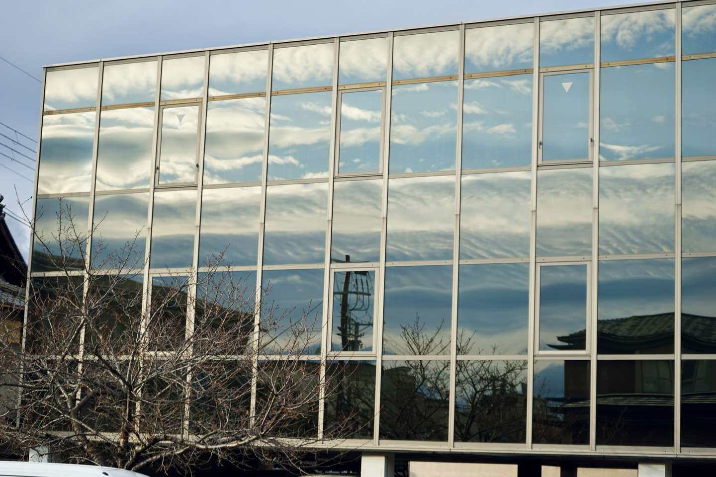
不得不說,京都真的非常適合徒步,不愧是步行友好城市。


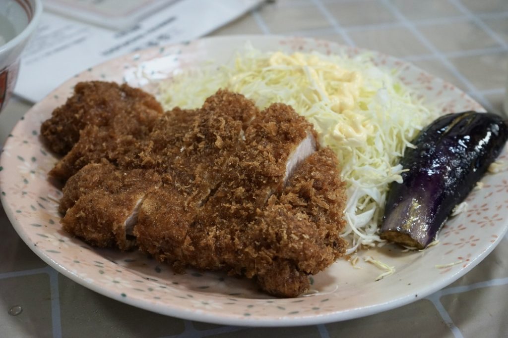
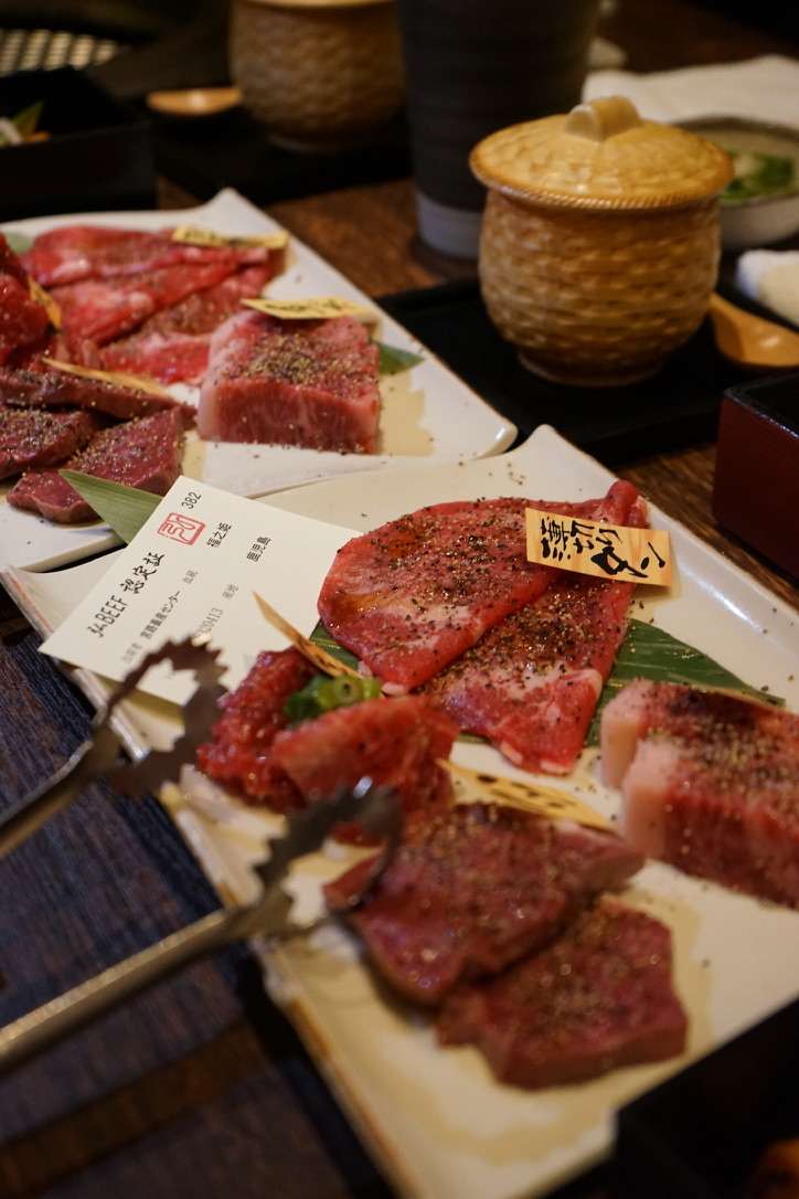
來京都怎麼也得喫一頓麥。

這就是第一天晚上將我們拒之門外的弘烤肉。這一家店的價格還是蠻高的。
我與友人在前往南禪寺的路上發現的小餐館。

體驗了一鰻三喫。
價格也比較感人。

比較有特色的就是這個鯖魚。是冷的,口感比較像鯪魚罐頭,味道來說比較清淡。

也許很難再有這樣的機會,能與友人去想去的地方了。
人生苦短,且行且珍惜。

项目(BIRP)在Github:
https://github.com/Remyuu/Unity-Interactive-Grass


先放一张10, 0500棵草在Compute Shader上未经任何优化在我的M1 pro上运行的截图,能跑个两百多帧。

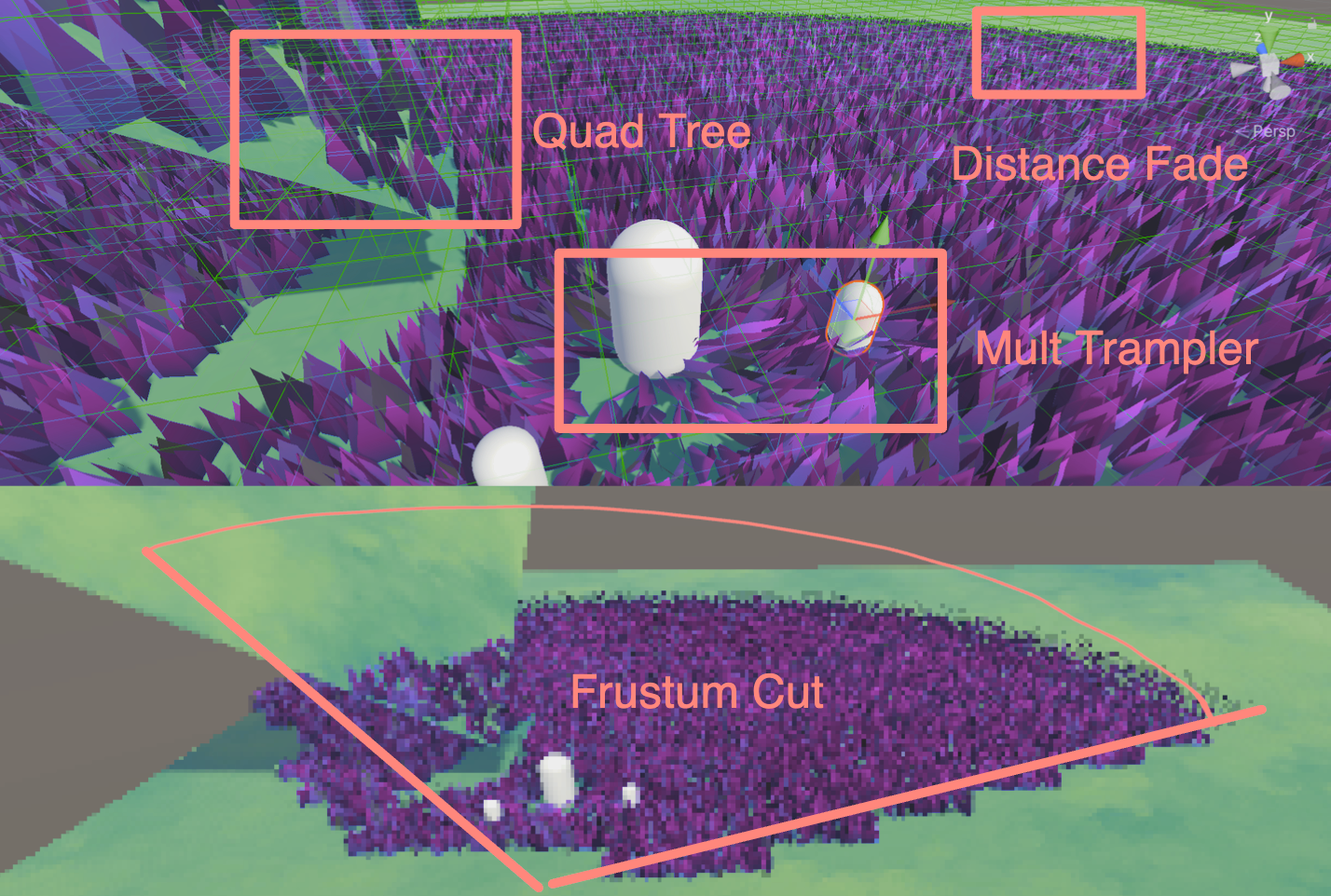
加入八叉树视锥体剔除、距离渐隐等操作,帧数反而没有这么稳定了(想死),我猜测是CPU端每一帧的操作压力太大,需要维护这么大量的草地信息。但是只要剔除得足够多,跑个700帧+是没问题的(安慰)。另外,八叉树的深度也需要根据实际做优化,下图八叉树的深度我设置为了5。

这篇文章已经越来越长了,主要留给自己回顾知识用,大佬们阅读的时候可能会感觉很多基础的内容。我是纯新手,恳求各位大佬的讨论和指正。

本文主要有两阶段:
几何着色器+曲面细分着色器的渲染方式应该是比较简单的,但是性能上限比较低,且平台兼容性差。
计算着色器配合GPU Instancing的方法应该才是当前业界的主流方法,并且在移动端上也能很好的运行。

本文的CS渲染草海Demo主要参考了Colin和Minions Art的实现,更类似两者的杂交低级版(前者知乎上已经有大佬解析过了基于GPU Instance的草地渲染学习笔记)。用三组ComputeBuffer,一组是包含所有草的Buffer,一个是Append丢进Material的Buffer,另一组是一个可见Buffer(根据视锥剔除实时得到)。实现了用一颗四八叉树(奇偶深度)来做空间划分,加上通过视锥剔除得到当前视锥体内的所有草的索引,传给Compute Shader做进一步的处理(例如Mesh生成、四元数计算旋转、LoD等操作),然后再用一个变长的ComputeBuffer(ComputeBufferType.Append)将需要渲染的草,通过Instancing传给Material做最终的渲染。
还可以用Hi-Z的方案做剔除,挖一个坑,努力学习中。
另外参考了Minions Art大佬的文章复刻了一套编辑器刷草的工具(残缺版),通过维护一个顶点列表,存储所有的草地顶点位置。
再进一步的,通过另外维护一组Cut Buffer,如果被标记为 -1 值的草,则不做处理。如果标记为砍刀高度的非 -1 数值,则会传到Material中,通过WorldPos + Split.y再加上lerp的操作,将草的上半部分变得不可见,并且再修改草的颜色,最后加上一些草屑的例子效果,实现一个砍草的效果。

上一篇文章已经详细介绍了什么是曲面细分着色器,以及各种优化方法。接下来将曲面细分融入实际开发。另外,结合了几天速成的Compute Shader,捣鼓出了基于计算着色器的草地,详细可以这一篇笔记。以下是本文将要实现的小效果,并附完整代码:
主要参考(抄袭)文章:
草地渲染有很多种方案,本文中的两种:
首先,第一种方案局限性很大。很多移动设备还有Metal不支持GS,而且GS每一帧都会重新计算一次Mesh,开销还是挺大的。
其次,MacOS就不能跑几何着色器了吗?也不是。想要用GS,就必须使用OpenGL,而不是Metal。但是需要注意,Apple对OpenGL最高支持到OpenGL 4.1。也就是说,这个版本不支持Compute Shader。当然,Intel时期的MacOS可以支持到OpenGL 4.3,可以同时跑CS和GS。M系列芯片就没这个命运了,要么用4.1,要么老老实实用Metal。在我的M1p mbp上,即使选择虚拟机(Parallels 18+ 提供了DX11和Vulkan),但是运行在macOS上的Vulkan是经过转译的,本质还是Metal,所以还是没GS。因此macOS M1之后就没有原生的GS了。
再者,Metal 甚至不直接支持 Tessellation 着色器。Apple压根不想在芯片上对这两个东西做支持。为什么呢?因为效率太低了。在M芯片上,TS甚至都是用CS模拟的!
总结一下,几何着色器是一个没有出路的技术,尤其是在Mesh Shader问世之后。虽然GS在Unity中很流行,但任何类似的效果都可以在CS上Instance出来,并且效率更高。现在的新显卡虽然还是会支持GS,因为目前市面上还是有相当多的游戏在用GS。只是Apple不考虑兼容性,直接砍掉了。

这篇文章详细讲述了为啥GS这么慢:http://www.joshbarczak.com/blog/?p=667。简单的说就是,Intel通过阻塞线程等方式优化了GS,其他芯片则没有这种优化。
本文作为学习笔记,很有可能会出错。
Domain Stage之后,可以选择使用几何着色器。

几何着色器将整个基元作为输入,并能够在输出上生成顶点。几何着色器的输入是完整基元的顶点(三角形为三个顶点,线为两个顶点或点为单个顶点)。每个基元都将调用一次几何着色器。
从网页下载初始工程。
绘制一个三角形。
// Add inside the CGINCLUDE block.
struct geometryOutput
{
    float4 pos : SV_POSITION;
};

...
    //顶点着色器
return vertex;
...

[maxvertexcount(3)]
void geo(triangle float4 IN[3] : SV_POSITION, inout TriangleStream<geometryOutput> triStream)
{
    geometryOutput o;

    o.pos = UnityObjectToClipPos(float4(0.5, 0, 0, 1));
    triStream.Append(o);

    o.pos = UnityObjectToClipPos(float4(-0.5, 0, 0, 1));
    triStream.Append(o);

    o.pos = UnityObjectToClipPos(float4(0, 1, 0, 1));
    triStream.Append(o);
}

…

// Add inside the SubShader Pass, just below the #pragma fragment frag line.
#pragma geometry geo
實際上,我們為網格中的每個頂點繪製了一個三角形,但我們分配給三角形頂點的位置是恆定的 – 它們不會針對每個輸入頂點而改變 – 將所有三角形放置在彼此之上了。
因此,根据每一个顶点位置做偏移即可。
// Add to the top of the geometry shader.
float3 pos = IN[0];

…

// Update each assignment of o.pos.
o.pos = UnityObjectToClipPos(pos + float3(0.5, 0, 0));

…

o.pos = UnityObjectToClipPos(pos + float3(-0.5, 0, 0));

…

o.pos = UnityObjectToClipPos(pos + float3(0, 1, 0));但是需要注意,目前三角形都是一个方向发射,因此加入法线修正。构建TBN矩阵,与当前给的方向做乘积。并且整理代码。
float3 vNormal = IN[0].normal;
float4 vTangent = IN[0].tangent;
float3 vBinormal = cross(vNormal, vTangent) * vTangent.w;

float3x3 tangentToLocal = float3x3(
    vTangent.x, vBinormal.x, vNormal.x,
    vTangent.y, vBinormal.y, vNormal.y,
    vTangent.z, vBinormal.z, vNormal.z
    );

triStream.Append(VertexOutput(pos + mul(tangentToLocal, float3(0.5, 0, 0))));
triStream.Append(VertexOutput(pos + mul(tangentToLocal, float3(-0.5, 0, 0))));
triStream.Append(VertexOutput(pos + mul(tangentToLocal, float3(0, 0, 1))));
然后定义草的上下两个颜色,用uv做lerp渐变。
return lerp(_BottomColor, _TopColor, i.uv.y);
做随机朝向。这里构建了一个旋转矩阵。原理在GAMES101也有讲到哦。B站还有一个公式推导的视频,讲得也很清晰!简单的推导思路就是,假設是向量 $a$ 繞著n軸旋轉至 $b$ ,則將 $a$ 分解為平行於n軸的分量(發現是不變的)加上垂直於n軸的分量。

float3x3 AngleAxis3x3(float angle, float3 axis)
{
    float c, s;
    sincos(angle, s, c);

    float t = 1 - c;
    float x = axis.x;
    float y = axis.y;
    float z = axis.z;

    return float3x3(
        t * x * x + c, t * x * y - s * z, t * x * z + s * y,
        t * x * y + s * z, t * y * y + c, t * y * z - s * x,
        t * x * z - s * y, t * y * z + s * x, t * z * z + c
        );
}
旋转矩阵 $R$ 这里用罗德里格旋转公式(Rodrigues’ rotation formula)来计算: $$R=I+sin(θ)⋅[k]×+(1−cos(θ))⋅[k]×2$$
其中, $\theta$ 是旋转角。$k$ 是单位旋转轴。 $I$ 是单位矩阵。 $[k]_{\times}$ 是轴 $k$ 对应的反对称矩阵。
对于一个单位向量 $k=(x,y,z)$ , 反对称矩阵 $[k]_{\times}=\left[\begin{array}{ccc} 0 & -z & y \\ z & 0 & -x \\ -y & x & 0 \end{array}\right]$ 最后得到的矩阵元素:
$$ \begin{array}{ccc} tx^2 + c & txy – sz & txz + sy \\ txy + sz & ty^2 + c & tyz – sx \\ txz – sy & tyz + sx & tz^2 + c \\ \end{array} $$
float3x3 facingRotationMatrix = AngleAxis3x3(rand(pos) * UNITY_TWO_PI, float3(0, 0, 1));
得到随机方向朝向的草,接下来在x或者y轴任意随机方向倾倒。
float3x3 bendRotationMatrix = AngleAxis3x3(rand(pos.zzx) * _BendRotationRandom * UNITY_PI * 0.5, float3(-1, 0, 0));
调整草的宽与高。原本我们默认高和宽都是一个单位。为了让草更加自然,这个步骤再加入rand,显得更加自然。
_BladeWidth("Blade Width", Float) = 0.05
_BladeWidthRandom("Blade Width Random", Float) = 0.02
_BladeHeight("Blade Height", Float) = 0.5
_BladeHeightRandom("Blade Height Random", Float) = 0.3


float height = (rand(pos.zyx) * 2 - 1) * _BladeHeightRandom + _BladeHeight;
float width = (rand(pos.xzy) * 2 - 1) * _BladeWidthRandom + _BladeWidth;


triStream.Append(VertexOutput(pos + mul(transformationMatrix, float3(width, 0, 0)), float2(0, 0)));
triStream.Append(VertexOutput(pos + mul(transformationMatrix, float3(-width, 0, 0)), float2(1, 0)));
triStream.Append(VertexOutput(pos + mul(transformationMatrix, float3(0, 0, height)), float2(0.5, 1)));
由于数量太少,此处上曲面细分。

让草动起来,加法线随着 _Time 扰动。采样贴图,然后计算风的旋转矩阵,应用到草上。
float2 uv = pos.xz * _WindDistortionMap_ST.xy + _WindDistortionMap_ST.zw + _WindFrequency * _Time.y;

float2 windSample = (tex2Dlod(_WindDistortionMap, float4(uv, 0, 0)).xy * 2 - 1) * _WindStrength;

float3 wind = normalize(float3(windSample.x, windSample.y, 0));

float3x3 windRotation = AngleAxis3x3(UNITY_PI * windSample, wind);

float3x3 transformationMatrix = mul(mul(mul(tangentToLocal, windRotation), facingRotationMatrix), bendRotationMatrix);此时风可能会沿着x和y轴的旋转,具体表现就是:

将脚下的两个点单独写一个只沿着z旋转的矩阵。
float3x3 transformationMatrixFacing = mul(tangentToLocal, facingRotationMatrix);

…

triStream.Append(VertexOutput(pos + mul(transformationMatrixFacing, float3(width, 0, 0)), float2(0, 0)));
triStream.Append(VertexOutput(pos + mul(transformationMatrixFacing, float3(-width, 0, 0)), float2(1, 0)));为了让叶子具有曲率,就只能增加顶点。另外,由于当前开启了双面渲染,顶点的顺序就没什么所谓了。这里手动插值for loop构建三角形。计算一个 forward 用于弯曲叶片。
float forward = rand(pos.yyz) * _BladeForward;


for (int i = 0; i < BLADE_SEGMENTS; i++)
{
    float t = i / (float)BLADE_SEGMENTS;
    // Add below the line declaring float t.
    float segmentHeight = height * t;
    float segmentWidth = width * (1 - t);
    float segmentForward = pow(t, _BladeCurve) * forward;
    float3x3 transformMatrix = i == 0 ? transformationMatrixFacing : transformationMatrix;
    triStream.Append(GenerateGrassVertex(pos, segmentWidth, segmentHeight, segmentForward, float2(0, t), transformMatrix));
    triStream.Append(GenerateGrassVertex(pos, -segmentWidth, segmentHeight, segmentForward, float2(1, t), transformMatrix));
}

triStream.Append(GenerateGrassVertex(pos, 0, height, forward, float2(0.5, 1), transformationMatrix));

在另外一个Pass中制造阴影,输出。
Pass{
    Tags{
        "LightMode" = "ShadowCaster"
    }

    CGPROGRAM
    #pragma vertex vert
    #pragma geometry geo
    #pragma fragment frag
    #pragma hull hull
    #pragma domain domain
    #pragma target 4.6
    #pragma multi_compile_shadowcaster

    float4 frag(geometryOutput i) : SV_Target{
        SHADOW_CASTER_FRAGMENT(i)
    }

    ENDCG
}
直接在Frag用 SHADOW_ATTENUATION 判断阴影。
// geometryOutput struct.
unityShadowCoord4 _ShadowCoord : TEXCOORD1;
...
o._ShadowCoord = ComputeScreenPos(o.pos);
...
#pragma multi_compile_fwdbase
...
return SHADOW_ATTENUATION(i);

去除表面痤疮。
#if UNITY_PASS_SHADOWCASTER
    o.pos = UnityApplyLinearShadowBias(o.pos);
#endif
给几何着色器生成的顶点加法线信息。
struct geometryOutput
{
    float4 pos : SV_POSITION;
    float2 uv : TEXCOORD0;
    unityShadowCoord4 _ShadowCoord : TEXCOORD1;
    float3 normal : NORMAL;
};
...
o.normal = UnityObjectToWorldNormal(normal);

最终效果。

代码:
完整的:https://pastebin.com/U14m1Nu0
刚才已经写了BIRP版本,现在只需要移植一下就好了。
大家可以跟着Daniel的这篇文章从头写一遍,也可以跟着我修改刚刚的代码。需要注意的是,原repo的空间变换代码是存在问题的,可以在Pull request中找到解决方案。
现将上面BIRP的曲面细分着色器整理到一起。
声明URP管线。
LOD 100
Cull Off
Pass{
    Tags{
        "RenderType" = "Opaque"
        "Queue" = "Geometry"
        "RenderPipeline" = "UniversalPipeline"
    }
导入URP的库。
#include "Packages/com.unity.render-pipelines.universal/ShaderLibrary/Core.hlsl"
#include "Packages/com.unity.render-pipelines.universal/ShaderLibrary/Lighting.hlsl"
#include "Packages/com.unity.render-pipelines.universal/ShaderLibrary/ShaderVariablesFunctions.hlsl"

o._ShadowCoord = ComputeScreenPos(o.pos);
改一下函数。
// o.normal = UnityObjectToWorldNormal(normal);
o.normal = TransformObjectToWorldNormal(normal);
URP接收阴影。这里最好在顶点着色器计算,但是为了方便就全放在几何着色器计算了。

然后生成阴影。ShadowCaster Pass。
Pass{
    Name "ShadowCaster"
    Tags{ "LightMode" = "ShadowCaster" }

    ZWrite On
    ZTest LEqual

    HLSLPROGRAM

        half4 frag(geometryOutput input) : SV_TARGET{
            return 1;
        }

    ENDHLSL
}
上面我们都只是采用固定数量的细分等级,我不能接受。如果不了解曲面细分原理的可以看我的曲面细分文章,里面详细讲了几种优化细分的方案。
我用第一节完成的BIRP版本的代码为例子。当前版本只有Uniform的细分。

_TessellationUniform("Tessellation Uniform", Range(1, 64)) = 1
当前各个阶段输出的结构体相当混乱,重新整理一下。


[KeywordEnum(INTEGER, FRAC_EVEN, FRAC_ODD, POW2)] _PARTITIONING("Partition algoritm", Float) = 0

#pragma shader_feature_local _PARTITIONING_INTEGER _PARTITIONING_FRAC_EVEN _PARTITIONING_FRAC_ODD _PARTITIONING_POW2

#if defined(_PARTITIONING_INTEGER)
    [partitioning("integer")]
#elif defined(_PARTITIONING_FRAC_EVEN)
    [partitioning("fractional_even")]
#elif defined(_PARTITIONING_FRAC_ODD)
    [partitioning("fractional_odd")]
#elif defined(_PARTITIONING_POW2)
    [partitioning("pow2")]
#else
    [partitioning("integer")]
#endif在BIRP中,使用 _ProjectionParams.z 表示远平面,URP中使用UNITY_RAW_FAR_CLIP_VALUE 。
bool IsOutOfBounds(float3 p, float3 lower, float3 higher) { //给定矩形判断
    return p.x < lower.x || p.x > higher.x || p.y < lower.y || p.y > higher.y || p.z < lower.z || p.z > higher.z;
}
bool IsPointOutOfFrustum(float4 positionCS) { //视锥体判断
    float3 culling = positionCS.xyz;
    float w = positionCS.w;
    float3 lowerBounds = float3(-w, -w, -w * _ProjectionParams.z);
    float3 higherBounds = float3(w, w, w);
    return IsOutOfBounds(culling, lowerBounds, higherBounds);
}
bool ShouldClipPatch(float4 p0PositionCS, float4 p1PositionCS, float4 p2PositionCS) {
    bool allOutside = IsPointOutOfFrustum(p0PositionCS) &&
        IsPointOutOfFrustum(p1PositionCS) &&
        IsPointOutOfFrustum(p2PositionCS);
    return allOutside;
}

TessellationControlPoint vert(Attributes v)
{
    ...
    o.positionCS = UnityObjectToClipPos(v.vertex);
    ...
}

TessellationFactors patchConstantFunction (InputPatch<TessellationControlPoint, 3> patch)
{
    TessellationFactors f;
    if(ShouldClipPatch(patch[0].positionCS, patch[1].positionCS, patch[2].positionCS)){
        f.edge[0] = f.edge[1] = f.edge[2] = f.inside = 0;
    }else{
        f.edge[0] = _TessellationFactor;
        f.edge[1] = _TessellationFactor;
        f.edge[2] = _TessellationFactor;
        f.inside = _TessellationFactor;
    }
    return f;
}
但是需要注意的是,這裡傳入的判斷是草皮的CS座標。如果三角形草皮完全離開屏幕,但是草長得高還可能會在屏幕中,就會導致草突然消失的畫面BUG。這就看項目的需求了,如果是仰視角並且草地比較矮的項目,就可以使用這個操作。
仰視角問題不大。

如果是伏地魔視角,草地並不完整,過度剔除了。

實現近處的草密集,遠處的草稀疏,但是基於屏幕距離(CS空間)。這個方法會受到分辨率的影響。
float EdgeTessellationFactor(float scale, float4 p0PositionCS, float4 p1PositionCS) {
    float factor = distance(p0PositionCS.xyz / p0PositionCS.w, p1PositionCS.xyz / p1PositionCS.w) / scale;
    return max(1, factor);
}

TessellationFactors patchConstantFunction (InputPatch<TessellationControlPoint, 3> patch)
{
    TessellationFactors f;

    f.edge[0] = EdgeTessellationFactor(_TessellationFactor,
        patch[1].positionCS, patch[2].positionCS);
    f.edge[1] = EdgeTessellationFactor(_TessellationFactor,
        patch[2].positionCS, patch[0].positionCS);
    f.edge[2] = EdgeTessellationFactor(_TessellationFactor,
        patch[0].positionCS, patch[1].positionCS);
    f.inside = (f.edge[0] + f.edge[1] + f.edge[2]) / 3.0;


    #if defined(_CUTTESS_TRUE)
        if(ShouldClipPatch(patch[0].positionCS, patch[1].positionCS, patch[2].positionCS))
            f.edge[0] = f.edge[1] = f.edge[2] = f.inside = 0;
    #endif

    return f;
}
Tessellation Factor = 0.08


並且劃分模式不建議選取Frac,不然就會有強烈的抖動,非常晃眼睛。這種方法我不太喜歡。
计算 「两点间的距离」与「两顶点的中点与相机位置的距离」的比值。比值越大说明占据屏幕的空间就越大,需要更多的细分程度。
float EdgeTessellationFactor_WorldBase(float scale, float3 p0PositionWS, float3 p1PositionWS) {
    float length = distance(p0PositionWS, p1PositionWS);
    float distanceToCamera = distance(_WorldSpaceCameraPos, (p0PositionWS + p1PositionWS) * 0.5);
    float factor = length / (scale * distanceToCamera * distanceToCamera);
    return max(1, factor);
}
...
f.edge[0] = EdgeTessellationFactor_WorldBase(_TessellationFactor_WORLD_BASE,
    patch[1].vertex, patch[2].vertex);
f.edge[1] = EdgeTessellationFactor_WorldBase(_TessellationFactor_WORLD_BASE,
    patch[2].vertex, patch[0].vertex);
f.edge[2] = EdgeTessellationFactor_WorldBase(_TessellationFactor_WORLD_BASE,
    patch[0].vertex, patch[1].vertex);
f.inside = (f.edge[0] + f.edge[1] + f.edge[2]) / 3.0;

还有改进空间。调整草地的密集度,使得近距离的草地不太密集,而中距离的草地曲线更为平滑,引入非线性因子来控制距离与镶嵌因子的关系。
float EdgeTessellationFactor_WorldBase(float scale, float3 p0PositionWS, float3 p1PositionWS) {
    float length = distance(p0PositionWS, p1PositionWS);
    float distanceToCamera = distance(_WorldSpaceCameraPos, (p0PositionWS + p1PositionWS) * 0.5);
    // 使用平方根函数调整距离的影响,使中距离的镶嵌因子变化更平滑
    float adjustedDistance = sqrt(distanceToCamera);
    // 调整 scale 的影响,可能需要根据实际效果进一步微调这里的系数
    float factor = length / (scale * adjustedDistance);
    return max(1, factor);
}
这样就比较合适了。


顶点着色器读取贴图,传给曲面细分着色器,在PCF计算细分逻辑。
以FIXED模式为例:
_VisibilityMap("Visibility Map", 2D) = "white" {}
TEXTURE2D (_VisibilityMap);SAMPLER(sampler_VisibilityMap);
struct Attributes
{
    ...
    float2 uv : TEXCOORD0;
};
struct TessellationControlPoint
{
    ...
    float visibility : TEXCOORD1;
};
TessellationControlPoint vert(Attributes v){
    ...
    float visibility = SAMPLE_TEXTURE2D_LOD(_VisibilityMap, sampler_VisibilityMap, v.uv, 0).r;
    o.visibility    = visibility;
    ...
}
TessellationFactors patchConstantFunction (InputPatch<TessellationControlPoint, 3> patch){
    ...
    float averageVisibility = (patch[0].visibility + patch[1].visibility + patch[2].visibility) / 3; // 计算三个顶点灰度值的平均值
    float baseTessellationFactor = _TessellationFactor_FIXED;
    float tessellationMultiplier = lerp(0.1, 1.0, averageVisibility); // 根据平均灰度值调整因子
    #if defined(_DYNAMIC_FIXED)
        f.edge[0] = _TessellationFactor_FIXED * tessellationMultiplier;
        f.edge[1] = _TessellationFactor_FIXED * tessellationMultiplier;
        f.edge[2] = _TessellationFactor_FIXED * tessellationMultiplier;
        f.inside  = _TessellationFactor_FIXED * tessellationMultiplier;
...Grass Shader:

URP有一些地方不太一样,比如说计算ShadowBias,就需要下面这样,不展开了,自己看代码吧。
#if UNITY_PASS_SHADOWCASTER
    // o.pos = UnityApplyLinearShadowBias(o.pos);
    o.shadowCoord = TransformWorldToShadowCoord(ApplyShadowBias(posWS, norWS, 0));
#endif
Grass Shader:
URP和BIRP完全一致。
原理很简单,脚本传角色的世界坐标进来,然后根据设定好的半径、互动强度,将草压弯。
uniform float3 _PositionMoving; // 物体的位置
float _Radius; // 物体的交互半径
float _Strength; // 交互强度
在草地生成的循环中,计算每个草片段与物体之间的距离,并根据这个距离调整草地的位置。
float dis = distance(_PositionMoving, posWS); // 计算距离
float radiusEffect = 1 - saturate(dis / _Radius); // 根据距离计算效果衰减
float3 sphereDisp = pos - _PositionMoving; // 计算位置差
sphereDisp *= radiusEffect * _Strength; // 应用衰减和强度
sphereDisp = clamp(sphereDisp, -0.8, 0.8); // 限制最大位移
然后在各个草叶中计算新的位置。
// 应用交互效果
float3 newPos = i == 0 ? pos : pos + (sphereDisp * t);
triStream.Append(GenerateGrassVertex(newPos, segmentWidth, segmentHeight, segmentForward, float2(0, t), transformMatrix));
triStream.Append(GenerateGrassVertex(newPos, -segmentWidth, segmentHeight, segmentForward, float2(1, t), transformMatrix));
别忘了for loop外面,也就是最上面的顶点。
// 最后的草片段
float3 newPosTop = pos + sphereDisp;
triStream.Append(GenerateGrassVertex(newPosTop, 0, height, forward, float2(0.5, 1), transformationMatrix));
triStream.RestartStrip();
在URP中,使用 uniform float3 _PositionMoving 可能会导致SRP Batcher失败。


哪个物体需要添加交互,就绑定上去。
using UnityEngine;

public class ShaderInteractor : MonoBehaviour
{
    // Update is called once per frame
    void Update()
    {
        Shader.SetGlobalVector("_PositionMoving", transform.position);
    }
}Grass shader:
为什么是 v1.0 呢,因为我觉得这个计算着色器渲染草海的难度比较大,很多目前不会的以后可以慢慢完善进来。我也写了一些Compute Shader的笔记。
上面的Compute Shader笔记里面完整的写了如何从零用CS写一个程式化的草海。如果忘记了在这里重新回顾一下。

在初始化阶段CPU要做的事情还是很多的,首先定义草的Mesh、Buffer传递(草的宽度、高度随机、每个草生成的位置、草地的随机朝向、草的随机色深)、还要专门向Compute Shader传递最大的弯曲值、草地互动半径。
每一帧CPU还要向Compute Shader传递时间变量、风向、风力/速、风场缩放因子。
Compute Shader利用CPU传递的信息计算出草应该怎么转向,使用了四元数作为输出。
最后Shader通过实例化标示ID和所有计算结果,首先计算顶点偏移,然后应用四元数旋转,最后修改法线信息。
这个Demo其实可以进一步优化,比如将更多的计算放在Compute Shader中进行,比如生成Mesh的过程、草地的宽高、随机朝向倾倒等。还可以优化一下更多实时的参数调节变量。还可以将做各种优化剔除,比如传入相机位置通过距离来剔除、或者用视锥体剔除等等,这个剔除的过程就需要使用到一些原子操作。还可以多物体交互。还可以优化交互草地变形的逻辑,比如交互的程度与交互物体的距离呈次方的关系等。还可以增加引擎功能,开发出笔刷刷草的功能,这就有可能需要一套四叉树存储系统等等。
并且在Compute Shader中,能用向量一把梭哈就不要用标量。
首先先整理一下代码。将不需要每帧都发给Compute Shader的变量都放在一个函数统一初始化。将Inspector面板整理一下。(代码改动很多)

首先将基本上所有的计算都放在GPU上运行了,除了每个草的世界坐标在CPU中计算,通过一个Buffer传给GPU。

Buffer传输的大小则完全取决于地面Mesh的大小与设置的密度。也就是说,如果是超级大的开放世界,这个Buffer就会变得超级大。一个 5*5 大小的草地,将Density设置为0.5,就大约会发送 312576 个草数据,实际数据就会达到 4*312576*4=5001216 字节,按照CPU->GPU的传输速度为8 GB/s 来计算,大约需要传10毫秒左右。

万幸这个Buffer并不是每一帧都需要传输,但是也足够引起我们的重视。假如当前草地大小变大到 100*100,所需时间将翻数倍,很吓人。而且这其中很多顶点我们都可能用不到,这就造成了很大的性能浪费。
我在Compute Shader里面加入了生成perlin噪声的函数,还有xorshift128随机数生成算法。
// Perlin 随机数算法
float hash(float x, float y) {
    return frac(abs(sin(sin(123.321 + x) * (y + 321.123)) * 456.654));
}
float perlin(float x, float y){
    float col = 0.0;
    for (int i = 0; i < 8; i++) {
        float fx = floor(x); float fy = floor(y);
        float cx = ceil(x); float cy = ceil(y);
        float a = hash(fx, fy); float b = hash(fx, cy);
        float c = hash(cx, fy); float d = hash(cx, cy);
        col += lerp(lerp(a, b, frac(y)), lerp(c, d, frac(y)), frac(x));
        col /= 2.0; x /= 2.0; y /= 2.0;
    }
    return col;
}
// XorShift128 随机数算法 -- Edited 直接输出归一化数据
uint state[4];
void xorshift_init(uint s) {
    state[0] = s; state[1] = s | 0xffff0000u;
    state[2] = s << 16; state[3] = s >> 16;
}
float xorshift128() {
    uint t = state[3]; uint s = state[0];
    state[3] = state[2]; state[2] = state[1]; state[1] = s;
    t ^= t << 11u; t ^= t >> 8u;
    state[0] = t ^ s ^ (s >> 19u);
    return (float)state[0] / float(0xffffffffu);
}

[numthreads(THREADGROUPSIZE,1,1)]
void BendGrass (uint3 id : SV_DispatchThreadID)
{
    xorshift_init(id.x * 73856093u ^ id.y * 19349663u ^ id.z * 83492791u);
    ...
}
复盘一下,目前,在CPU用的是草地的一个AABB平均铺草的逻辑生成所有可能的草的顶点,然后传给GPU,在Compute Shader中做一些剔除、LoD等操作。

目前为止我搞了三个Buffer。

m_InputBuffer就是将所有的草一股脑传给GPU,没有任何剔除的。上图左边的结构体。
m_OutputBuffer是一个变长的Buffer,在Compute Shader中慢慢增加的。如果当前线程ID的草适合,就会被加到这个Buffer中,用于一会的Instanced渲染。上图右边的结构体。
m_argsBuffer是一个参数化的Buffer,类型和其他Buffer都不同的。最后用于Draw传参,具体内容就是指定了批量渲染的顶点数量、渲染实例数量等等。详细来看看:

第一个参数,我的草Mesh有七个三角形,所以要渲染21个顶点。
第二个参数暂时设置为0,表示啥也不需要渲染。这个数字会在Compute Shader计算结束后,根据m_OutputBuffer的长度来动态设置。也就是说,Compute Shader里Append了多少个草,这里就会变成多少。
第三第四个参数分别表示:第一个渲染的顶点的索引、第一个实例化的索引。
后面第五个参数我没用过,不知道有啥用。
最后一步长这样,把Mesh、材质、AABB还有参数Buffer传进去了。

新建一个C#脚本,存在项目的Editor目录下(没有就创建一个)。脚本继承自Editor,然后写上 [CustomEditor(typeof(XXX))] 。表示你是为XXX工作。我为GrassControl工作,然后可以将现在这个写的东西附加到XXX上。当然也可以单独一个窗口,应该就是继承自EditorWindow。

在 OnInspectorGUI() 函数中写工具。比方说写一个Label。
GUILayout.Label("== Remo Grass Generator ==");
想要在Inspector居中,加一段参数。
GUILayout.Label("== Remo Grass Generator ==", new GUIStyle(EditorStyles.boldLabel) { alignment = TextAnchor.MiddleCenter });
位置太挤了?加一行空格就好。
EditorGUILayout.Space();
想在XXX的上方附加工具,那所有逻辑就写在OnInspectorGUI的上方。
... // 写在这
// 默认的 GrassControl 的 Inspector 界面
base.OnInspectorGUI();
创建按钮,并且按下的代码:
if (GUILayout.Button("xxx"))
{
    ...//按下后的代码
反正目前我用到的就这些。
获取当前服务的脚本的Object,并且显示在Inspector上,也很简单。
[SerializeField] private GameObject grassObject;
...
grassObject = (GameObject)EditorGUILayout.ObjectField("名字随便写", grassObject, typeof(GameObject), true);
if (grassObject == null)
{
    grassObject = FindObjectOfType<GrassControl>()?.gameObject;
}
获取完了之后,就可以通过GameObject访问当前脚本里边的东西了。
如何获取在Editor窗口选中的对象呢?一行代码就搞掂。
foreach (GameObject obj in Selection.gameObjects)将选中的物体展示在Inspector面板上。注意,这里需要处理多选物体的情况,否则会Warning。
// 实时显示当前Editor选中对象并控制按钮的可用性
EditorGUILayout.LabelField("Selection Info:", EditorStyles.boldLabel);
bool hasSelection = Selection.activeGameObject != null;
GUI.enabled = hasSelection;
if (hasSelection)
    foreach (GameObject obj in Selection.gameObjects)
        EditorGUILayout.LabelField(obj.name);
else
    EditorGUILayout.LabelField("No active object selected.");
接下来获取选中对象的MeshFilter和Renderer,由于要Raycast检测,就再获取个Collider。若没有就创建一个。

然后写生草的代码,这里就不说了。
生成完一堆草后,要将每个草加到AABB里面,最后传给Instancing。

我假设每个草都是一个单位立方体的大小,所以是Vector3.one。如果草特别高,这里应该是需要修改的。
将每个草都塞进大的AABB中,将新的AABB传回给脚本的m_LocalBounds,给Instancing用。
Graphics.DrawMeshInstancedIndirect(blade, 0, m_Material, m_LocalBounds, m_argsBuffer);这里有个小问题,由于当前Material是Surface Shader,Surface Shader的Vertex已经默认计算了AABB的center做了顶点偏移,所以之前传进去的世界坐标就不能直接用。还需要传AABB的center进去,减掉才行。好奇怪啊,不知道有没有什么优雅的方法。

目前在CPU将所有生成的草都传进了Compute Shader中,然后所有的草都会加进AppendBuffer中。也就是说没有任何剔除逻辑可言。

最简单的剔除方案就是根据摄像机与草地的距离做剔除。在Inspector面板开放一个数值表示剔除距离。计算摄像机与当前草实例的距离,如果大于设定的数值,则不添加到AppendBuffer中。

首先在 C# 中传入相机的世界坐标。下面是半伪代码:
// 获取摄像机
private Camera m_MainCamera;

m_MainCamera = Camera.main;

if (m_MainCamera != null)
    m_ComputeShader.SetVector(ID_camreaPos, m_MainCamera.transform.position);
CS中,计算草地和摄像机的距离:
float distanceFromCamera = distance(input.position, _CameraPositionWS);
距离函数代码如下:
float distanceFade = 1 - saturate((distanceFromCamera - _MinFadeDist) / (_MaxFadeDist - _MinFadeDist));如果数值小于0,就直接return。
// skip if out of fading range too
if (distanceFade < 0.001f)
{
    return;
}
在剔除与不剔除之间的部分,设置一下草的宽度+Fade值,达到渐隐的效果。
result.height = (bladeHeight + bladeHeightOffset * (xorshift128()*2-1)) * distanceFade;
result.width = (bladeWeight + bladeWeightOffset * (xorshift128()*2-1)) * distanceFade;
...
result.fade = xorshift128() * distanceFade;
下图为了方便演示,把两个都设置得比较小。

实际效果我觉得还是很不错的,十分流畅。如果不修改草的宽高,效果就会大打折扣。
当然了,也可以修改一下逻辑:不要完全剔除超过最大绘制范围的草,而是减少绘制的数量;或者是在过渡区的草选择性的绘制。
两种逻辑都可以,如果是我我会选择后者。
所谓视锥体剔除,就是在CPU阶段,通过各种方法减少GPU多余的计算。
那怎么让Compute Shader知道哪些草需要渲染,哪些需要Cull呢?我的做法是维护一组ID List。长度是所有草的数量。如果当前草需要被剔除,否则就记录需要渲染的草的索引值。
List<uint> grassVisibleIDList = new List<uint>();

// buffer that contains the ids of all visible instances
private ComputeBuffer m_VisibleIDBuffer;

private const int VISIBLE_ID_STRIDE        =  1 * sizeof(uint);

m_VisibleIDBuffer = new ComputeBuffer(grassData.Count, VISIBLE_ID_STRIDE,
    ComputeBufferType.Structured); //uint only, per visible grass
m_ComputeShader.SetBuffer(m_ID_GrassKernel, "_VisibleIDBuffer", m_VisibleIDBuffer);

m_VisibleIDBuffer?.Release();
既然在传入Compute Shader之前,就已经有一部分草被剔除了,那么Dispatch的数量就不再是所有草的数量,而是当前List的数量。
// m_ComputeShader.Dispatch(m_ID_GrassKernel, m_DispatchSize, 1, 1);

m_DispatchSize = Mathf.CeilToInt(grassVisibleIDList.Count / threadGroupSize);
生成一个全部可视的ID序列。
void GrassFastList(int count)
{
    grassVisibleIDList = Enumerable.Range(0, count).ToArray().ToList();
}
并且每一帧都应用上传到GPU中。准备工作就完成了,接下来用Quad树操作这个数组。
可以考虑将一个AABB划分为多个子AABB,然后用四叉树存储管理。

目前,所有的草都在一个AABB里面。接下来构建一个八叉树,将这个AABB中的所有草都放进各个分支中。这样就很方便的在CPU前期做视锥体剔除。

怎么存呢?如果当前的草地垂直落差较小,那么用四叉树就足够了。那如果是开放世界,山脉高低起伏的,那就用八叉树。但是考虑到草是水平的密度比较高,我这里使用了一个四叉树+八叉树的结构。根据深度的奇偶来决定当前深度是分四个节点还是八个节点。如果不需要强烈的高度划分,就全用八叉树也行,我感觉效率可能会低一点点。这里直接一把平均分配,后期优化可以考虑根据变长动态变化的划分AABB方式。
if (depth % 2 == 0)
{
    ...
    m_children.Add(new CullingTreeNode(topLeftSingle, depth - 1));
    m_children.Add(new CullingTreeNode(bottomRightSingle, depth - 1));
    m_children.Add(new CullingTreeNode(topRightSingle, depth - 1));
    m_children.Add(new CullingTreeNode(bottomLeftSingle, depth - 1));
}
else
{
    ...
    m_children.Add(new CullingTreeNode(topLeft, depth - 1));
    m_children.Add(new CullingTreeNode(bottomRight, depth - 1));
    m_children.Add(new CullingTreeNode(topRight, depth - 1));
    m_children.Add(new CullingTreeNode(bottomLeft, depth - 1));

    m_children.Add(new CullingTreeNode(topLeft2, depth - 1));
    m_children.Add(new CullingTreeNode(bottomRight2, depth - 1));
    m_children.Add(new CullingTreeNode(topRight2, depth - 1));
    m_children.Add(new CullingTreeNode(bottomLeft2, depth - 1));
}
视锥体与AABB的检测用 GeometryUtility.TestPlanesAABB 就好了。
public void RetrieveLeaves(Plane[] frustum, List<Bounds> list, List<int> visibleIDList)
{
    if (GeometryUtility.TestPlanesAABB(frustum, m_bounds))
    {
        if (m_children.Count == 0)
        {
            if (grassIDHeld.Count > 0)
            {
                list.Add(m_bounds);
                visibleIDList.AddRange(grassIDHeld);
            }
        }
        else
        {
            foreach (CullingTreeNode child in m_children)
            {
                child.RetrieveLeaves(frustum, list, visibleIDList);
            }
        }
    }
}
这段代码是关键部分,传入:
调用这个四/八叉树的方法,就可以得到所有在视锥体内的包围盒列表、草地列表。
然后就可以将得到的所有草地索引做成一个Buffer传给Compute Shader。
m_VisibleIDBuffer.SetData(grassVisibleIDList);为了得到可视化的AABB,可以用 OnDrawGizmos() 方法。

将刚刚视锥体剔除得到的所有AABB传进这个函数。这样就可以直观看到AABB了。


还要将所有在视锥体内的写入可见草中。

在这里我踩了一个小坑。当我完整了八叉树的编写,并且成功像上图一样划分出了诸多子AABB。但是当我移动摄像头的时候,草在疯狂闪烁。GIF视频啥的我有点懒不想弄,观察一下下面两张图,我只是稍微移动了一下视角,并且改变了当前Visibility List。草的位置就会大跳跃,连续地看就是草在闪烁。


我百思不得其解,Compute Shader的剔除也没问题。

Dispatch数量也是根据Visibility List的长度来运算的,因此计算着色器的线程肯定是开够的。

并且DrawMeshInstancedIndirect也没问题。

问题出在哪呢?
经过漫长的调试,我发现问题出在Compute Shader的Xorshift取随机数的过程。
在使用_VisibleIDBuffer之前,一个草对应一个线程ID,这是从草出生那一刻就已经决定的了。而现在加入了这一组索引,又不将传入随机值的ID改成 Visible ID ,就会出现随机数字非常离散的感觉。

也就是将之前的id全部都换成从_VisibleIDBuffer 取的索引值!

目前只有一个trampler传入。不传还会报错,不能忍。

关于交互的参数有三个:
现在将trampleRadius塞进pos(Vector4)里面(塞另外一个也行,看需求),用SetVectorArray将位置数组传进去。这样每个交互对象都可以拥有一个专用的交互半径。肥肥的交互物体半径调大一些,瘦瘦的就小一些。也就是将下面这行去掉:
// SetGrassDataBase中,不需要每帧上传
// m_ComputeShader.SetFloat("trampleRadius", trampleRadius);
变成:
// SetGrassDataUpdate中,每帧都要上传
// 设置多交互物体
if (trampler.Length > 0)
{
    Vector4[] positions = new Vector4[trampler.Length];
    for (int i = 0; i < trampler.Length; i++)
    {
        positions[i] = new Vector4(trampler[i].transform.position.x, trampler[i].transform.position.y, trampler[i].transform.position.z,
            trampleRadius);
    }
    m_ComputeShader.SetVectorArray(ID_tramplePos, positions);
}
然后还得传一个交互物体的数量,让Compute Shader知道需要处理多少个交互物体。这个也是需要每一帧更新的。我习惯为每一帧都更新的物体存储一个ID索引,这样效率更高。
// 初始化中
ID_trampleLength = Shader.PropertyToID("_trampleLength");
// 每帧中
m_ComputeShader.SetFloat(ID_trampleLength, trampler.Length);
我再包装了一下:


对应代码再修改一下,就可以在面板上随便调整每个交互物体的半径了。如果要丰富这个调节功能,可以考虑单独传一个Buffer进去。

在Compute Shader中,并且多个旋转组合起来,还是比较简单的。
// Trampler
float4 qt = float4(0, 0, 0, 1); // 四元数里的1就是这样的,虚部都是0
for (int trampleIndex = 0; trampleIndex < trampleLength; trampleIndex++)
{
    float trampleRadius = tramplePos[trampleIndex].a;
    float3 relativePosition = input.position - tramplePos[trampleIndex].xyz;
    float dist = length(relativePosition);
    if (dist < trampleRadius) {
        // 使用次方增强近距离的效果
        float eff = pow((trampleRadius - dist) / trampleRadius, 2) * trampleStrength;
        float3 direction = normalize(relativePosition);
        float3 newTargetDirection = float3(direction.x * eff, 1, direction.z * eff);
        qt = quatMultiply(MapVector(float3(0, 1, 0), newTargetDirection), qt);
    }
}
当前传给Compute Shader的摄像机是主相机,也就是游戏窗口那个。现在想要在编辑(Scene窗口)暂时得到主摄像机的镜头,启动游戏之后复原。可以使用 Scene View GUI 绘制事件。
以下是改造我当前代码的例子:
#if UNITY_EDITOR
    SceneView view;

    void OnDestroy()
    {
        // When the window is destroyed, remove the delegate
        // so that it will no longer do any drawing.
        SceneView.duringSceneGui -= this.OnScene;
    }

    void OnScene(SceneView scene)
    {
        view = scene;
        if (!Application.isPlaying)
        {
            if (view.camera != null)
            {
                m_MainCamera = view.camera;
            }
        }
        else
        {
            m_MainCamera = Camera.main;
        }
    }
    private void OnValidate()
    {
        // Set up components
        if (!Application.isPlaying)
        {
            if (view != null)
            {
                m_MainCamera = view.camera;
            }
        }
        else
        {
            m_MainCamera = Camera.main;
        }
    }
#endif
在初始化着色器的时候,在开头订阅事件,然后判断当前是否为游戏状态,是才传递一个摄像机。如果是编辑模式,那m_MainCamera这一项还是NULL。
void InitShader()
{
#if UNITY_EDITOR
    SceneView.duringSceneGui += this.OnScene;
    if (!Application.isPlaying)
    {
        if (view != null && view.camera != null)
        {
            m_MainCamera = view.camera;
        }
    }
#endif
    if (Application.isPlaying)
    {
        m_MainCamera = Camera.main;
    }
    ...
在逐帧Update的函数中,如果检测到m_MainCamera是NULL,那么断定当前是编辑模式:
// 传入摄像机坐标
        if (m_MainCamera != null)
            m_ComputeShader.SetVector(ID_camreaPos, m_MainCamera.transform.position);
#if UNITY_EDITOR
        else if (view != null && view.camera != null)
        {
            m_ComputeShader.SetVector(ID_camreaPos, view.camera.transform.position);
        }

#endif

维护一组Cut Buffer
// added for cutting
private ComputeBuffer m_CutBuffer;
float[] cutIDs;
初始化Buffer
private const int CUT_ID_STRIDE            =  1 * sizeof(float);
// added for cutting
m_CutBuffer = new ComputeBuffer(grassData.Count, CUT_ID_STRIDE, ComputeBufferType.Structured);
// added for cutting
m_ComputeShader.SetBuffer(m_ID_GrassKernel, "_CutBuffer", m_CutBuffer);
m_CutBuffer.SetData(cutIDs);
别忘了在Disable的时候释放。
// added for cutting
m_CutBuffer?.Release();
定义一个方法,传入当前位置和半径,计算草的位置。将对应cutID设为-1。
// newly added for cutting
public void UpdateCutBuffer(Vector3 hitPoint, float radius)
{
    // can't cut grass if there is no grass in the scene
    if (grassData.Count > 0)
    {
        List<int> grasslist = new List<int>();
        // Get the list of IDS that are near the hitpoint within the radius
        cullingTree.ReturnLeafList(hitPoint, grasslist, radius);
        Vector3 brushPosition = this.transform.position;
        // Compute the squared radius to avoid square root calculations
        float squaredRadius = radius * radius;

        for (int i = 0; i < grasslist.Count; i++)
        {
            int currentIndex = grasslist[i];
            Vector3 grassPosition = grassData[currentIndex].position + brushPosition;

            // Calculate the squared distance
            float squaredDistance = (hitPoint - grassPosition).sqrMagnitude;

            // Check if the squared distance is within the squared radius
            // Check if there is grass to cut, or of the grass is uncut(-1)
            if (squaredDistance <= squaredRadius && (cutIDs[currentIndex] > hitPoint.y || cutIDs[currentIndex] == -1))
            {
                // store cutting point
                cutIDs[currentIndex] = hitPoint.y;
            }

        }
    }
    m_CutBuffer.SetData(cutIDs);
}
然后在需要砍草的对象身上绑一个脚本:
using System.Collections;
using System.Collections.Generic;
using UnityEngine;


public class Cutgrass : MonoBehaviour
{
    [SerializeField]
    GrassControl grassComputeScript;

    [SerializeField]
    float radius = 1f;

    public bool updateCuts;

    Vector3 cachedPos;
    // Start is called before the first frame update


    // Update is called once per frame
    void Update()
    {
        if (updateCuts && transform.position != cachedPos)
        {
            Debug.Log("Cutting");
            grassComputeScript.UpdateCutBuffer(transform.position, radius);
            cachedPos = transform.position;

        }
    }

    private void OnDrawGizmos()
    {
        Gizmos.color = new Color(1, 0, 0, 0.3f);
        Gizmos.DrawWireSphere(transform.position, radius);
    }
}
在Compute Shader中,直接修改草的高度。(非常直截了当。。。)想改啥效果就随意了。
StructuredBuffer<float> _CutBuffer;// added for cutting

    float cut = _CutBuffer[usableID];
    result.height = (bladeHeight + bladeHeightOffset * (xorshift128()*2-1)) * distanceFade;
    if(cut != -1){
        result.height *= 0.1f;
    }
完工!

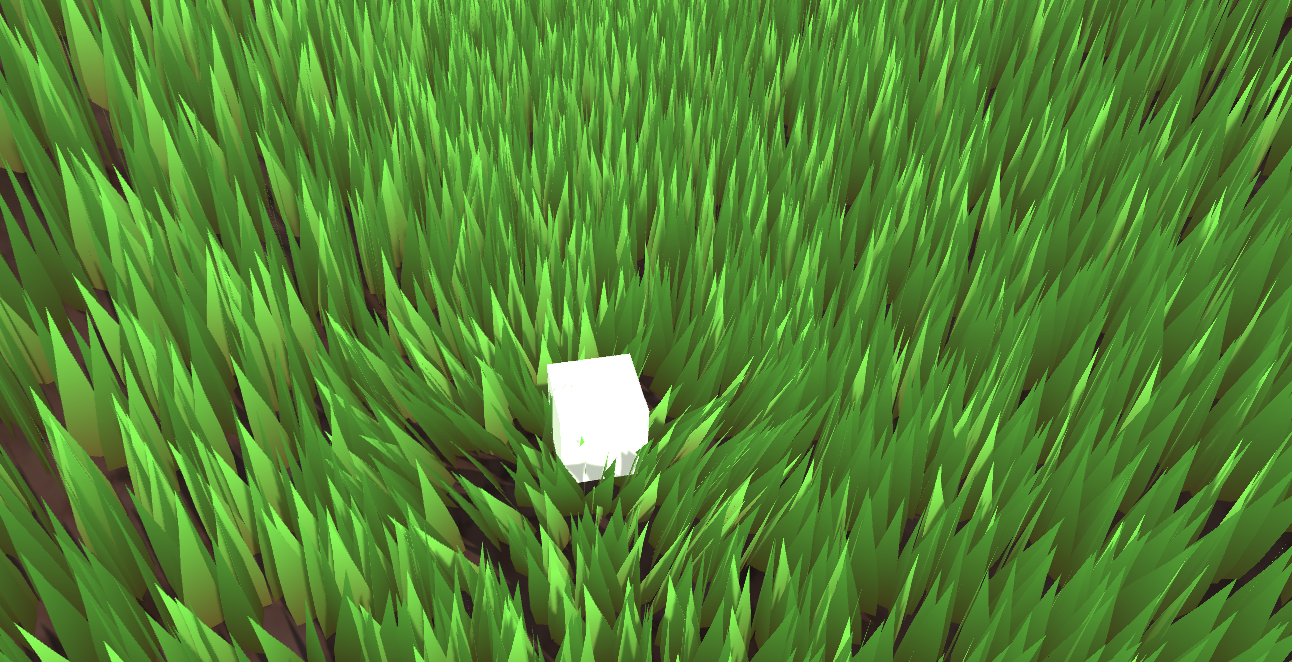
项目地址:
https://github.com/Remyuu/Unity-Compute-Shader-Learngithub.com/Remyuu/Unity-Compute-Shader-Learn


当前做的效果非常丑陋,还有很多细节没有完善,仅仅是“实现”了。由于我也是菜鸡,写/做的不够好的地方望各位指正。

知识点小结:
前言参考文章:

草地渲染有很多方法。
最简单的是直接一张草地的纹理贴上去。

除此之外,将一个个Mesh草拖到场景中也很常见。这种方法操作空间大,每一颗草都在掌控中。虽然可以用Batching等方法优化,减少CPU到GPU的传输时间,但是这会损耗您键盘上的Ctrl、C、V和D键的寿命。不过可以在Transform组件里面用 L(a, b) 让选中的物体平均分布在 a 和 b 之间。想随机,可以用 R(a, b) 。更多相关的操作可以看官方文档。

还可以结合几何着色器和曲面细分着色器,这个方法看起来不错的,但是一个着色器只能对应一种几何(草),如果想要在这个网格生成花或者岩石,就需要在几何着色器中修改代码。这个问题其实不是最关键的,更要命的问题是很多移动设备还有Metal根本就不支持几何着色器,就算支持也只是软件模拟的,性能差劲。并且每一帧都会重新计算一次草地Mesh,浪费性能。

广告牌技术渲染草也是一种广泛流传经久不衰的方法。当我们不需要高保真的画面时,这个方法非常奏效。这个方法是简单的渲一个Quad+贴图(Alpha裁切)。用DrawProcedural就可以了。但是这个方法只可远观不可近看,否则就会大露馅。

用Unity的地形系统也可以画出非常nice的草。并且Unity使用了instancing技术确保了性能。其中最好用的地方莫过于他的笔刷工具,但是如果你的工作流没有地形系统的身影,那么你还可以用第三方插件做到。

在搜索资料的时候我还发现了一种叫Impostors「冒名顶替」技术。结合了广告牌的顶点节省优势和从多个角度真实重现对象的能力,还挺有意思。这个技术通过预先从多个角度“拍下”一个真实草的Mesh照片,通过Texture存起来。运行的时候根据当前相机的观看方向选择合适的纹理进行渲染。相当于广告牌技术的升级版。我认为Impostors技术非常适合用于那些大型但玩家可能需要从多个角度查看的对象,如树木或复杂建筑。然而,当相机非常接近或者在两个角度之间变换时,这种方法可能会出现问题。比较合理的方案是:在距离非常近用基于Mesh的方法,中等距离用Impostors,远距离用广告牌。

本文要实现的方法是基于GPU Instancing的,应该称之为「per-blade mesh grass」。在《對馬島之魂》、《原神》和《薩爾達傳說:曠野之息》等游戏上都是使用这种方案。每个草都有自己的实体,光影效果也相当真实。

渲染流程:

Unity的Instancing技术比较复杂,我也只是管中窥豹,出现错误请指正。目前的代码都是仿照文档写的。GPU instancing目前支持的平台:
另外Graphics.DrawMeshInstancedIndirect目前已经淘汰了,应该使用 Graphics.RenderMeshIndirect ,这个函数会自动计算Bounding Box,这个就是后话了。详细请看官方文档:RenderMeshIndirect 。这篇文章也很有帮助:
https://zhuanlan.zhihu.com/p/403885438。
GPU Instancing原理是将多个具有相同Mesh的对象发一次Draw Call。CPU首先收集好所有信息,然后放到数组里一次性发给GPU。局限就是这些对象的Material和Mesh都要相同。这就是一次能绘制这么多草而保持高性能的原理。要实现GPU Instancing绘制上百万的Mesh,就需要遵循一些规定:
由于不支持Skin Mesh Renderer,在上一篇文章中,我们绕过了SMR,直接取了不同关键帧的Mesh出来传给GPU,这也是上一篇文章最后提出那个问题的原因。
Unity中的Instancing分为两种主要类型:GPU Instancing和Procedural Instancing(涉及到Compute Shaders和Indirect Drawing技术),还有一种是立体渲染路径(UNITY_STEREO_INSTANCING_ENABLED),这里就不深入了。在Shader中,前者用#pragma multi_compile_instancing 后者用#pragma instancing_options procedural:setup 。具体的请看官方文档Creating shaders that support GPU instancing 。
然后目前SRP管线不支持自定义的GPU Instancing Shader,只有BIRP可以。
然后就是UNITY_PROCEDURAL_INSTANCING_ENABLED 。这个宏用于表示是否启用了Procedural Instancing。在使用Compute Shader或Indirect Drawing API时,实例的属性(如位置、颜色等)可以在GPU上实时计算并直接用于渲染,无需CPU的介入。在源代码中,关于这个宏的核心代码是:
#ifdef UNITY_PROCEDURAL_INSTANCING_ENABLED
    #ifndef UNITY_INSTANCING_PROCEDURAL_FUNC
        #error "UNITY_INSTANCING_PROCEDURAL_FUNC must be defined."
    #else
        void UNITY_INSTANCING_PROCEDURAL_FUNC(); // 前向声明程序化函数
        #define DEFAULT_UNITY_SETUP_INSTANCE_ID(input)      { UnitySetupInstanceID(UNITY_GET_INSTANCE_ID(input)); UNITY_INSTANCING_PROCEDURAL_FUNC();}
    #endif
#else
    #define DEFAULT_UNITY_SETUP_INSTANCE_ID(input)          { UnitySetupInstanceID(UNITY_GET_INSTANCE_ID(input));}
#endif
要求Shader定义一个UNITY_INSTANCING_PROCEDURAL_FUNC函数,其实就是 setup() 函数。没有这个setup()函数,就会报错。
一般来说,setup()函数要做的就是从Buffer中取出对应(unity_InstanceID) 的数据,然后计算当前实例的位置、变换矩阵、颜色、金属度或者是自定义数据等属性。
GPU Instancing只是Unity众多优化手段的一种,仍然需要继续学习。
这一章所运用关于CS的知识点在上一篇文章都已全部涉及,只不过换一个背景罢了。简单画一个示意图。

实现是使用GPU Instancing,也就是一次性渲染一大片Mesh。核心的代码就一句:
Graphics.DrawMeshInstancedIndirect(mesh, 0, material, bounds, argsBuffer);Mesh采用三个Quad共六个三角形组成。

然后上一张贴图+Alpha Test。

草的数据结构:
public Vector3 position; // 世界坐标,需要计算
public float lean;
public float noise;
public GrassClump( Vector3 pos){
    position.x = pos.x;
    position.y = pos.y;
    position.z = pos.z;
    lean = 0;
    noise = Random.Range(0.5f, 1);
    if (Random.value < 0.5f) noise = -noise;
}
将需要渲染的草的Buffer(世界坐标需要计算)传给GPU。首先确定草在哪里生成、生成多少。获取当前物体的Mesh(暂时假设是一个Plane Mesh)的AABB。
Bounds bounds = mf.sharedMesh.bounds;
Vector3 clumps = bounds.extents;
确定草的范围,然后在xOz平面上随机生成草。

添加图片注释,不超过 140 字(可选)
需要注意,当前还是在物体空间,因此需要将Object Space转换到World Space。
pos = transform.TransformPoint(pos);再结合密度density参数和物体缩放系数,计算出一共要渲染多少个草。
Vector3 vec = transform.localScale / 0.1f * density;
clumps.x *= vec.x;
clumps.z *= vec.z;
int total = (int)clumps.x * (int)clumps.z;
由于Compute Shader的逻辑是每个线程计算一棵草,极有可能需要渲染的草的数量不是线程的倍数。因此将需要渲染的草的数量向上取整到线程的倍数。也就是说,当密度因子=1的时候,渲染的草的数量等于一个线程组中线程的数量。
groupSize = Mathf.CeilToInt((float)total / (float)threadGroupSize);
int count = groupSize * (int)threadGroupSize;
让Compute Shader计算每个草的倾斜角度。
GrassClump clump = clumpsBuffer[id.x];
clump.lean = sin(time) * maxLean * clump.noise;
clumpsBuffer[id.x] = clump;
将草的位置、旋转角度传给GPU Buffer还没完,还得拜托Material决定渲染实例的最终外观,才能最终执行Graphics.DrawMeshInstancedIndirect。
渲染流程中,在实例化阶段之前(也就是procedural:setup函数内),使用unity_InstanceID确定现在渲的是哪个草。获取当前草的世界空间,草的倾倒值。
GrassClump clump = clumpsBuffer[unity_InstanceID];
_Position = clump.position;
_Matrix = create_matrix(clump.position, clump.lean);
具体的旋转+位移矩阵:
float4x4 create_matrix(float3 pos, float theta){
    float c = cos(theta); // 计算旋转角度的余弦值
    float s = sin(theta); // 计算旋转角度的正弦值
    // 返回一个4x4变换矩阵
    return float4x4(
        c, -s, 0, pos.x, // 第一行:X轴旋转和位移
        s,  c, 0, pos.y, // 第二行:Y轴旋转(对于2D足够,但草丛可能不使用)
        0,  0, 1, pos.z, // 第三行:Z轴不变
        0,  0, 0, 1     // 第四行:均匀坐标(保持不变)
    );
}
这个公式怎么推的呢?将(0,0,1)带入罗德里格斯公式得到一个的旋转矩阵,然后扩展到重心坐标。带入 就是代码的公式了。

用这个矩阵乘上Object Space的顶点,得到倾倒+位移的顶点坐标。
v.vertex.xyz *= _Scale;
float4 rotatedVertex = mul(_Matrix, v.vertex);
v.vertex = rotatedVertex;
这时候问题来了。目前草并不是一个平面,而是三组Quad组成的立体图形。

如果简单的将所有顶点按照z轴旋转,就会出现草根大偏移的问题。

因此借助 v.texcoord.y ,将旋转前后的顶点位置lerp起来。这样,纹理坐标的Y值越高(即顶点在模型上的位置越靠近顶部),顶点受到的旋转影响就越大。由于草根的Y值为0,lerp之后草根就不会乱晃了。
v.vertex.xyz *= _Scale;
float4 rotatedVertex = mul(_Matrix, v.vertex);
// v.vertex = rotatedVertex;
v.vertex.xyz += _Position;
v.vertex = lerp(v.vertex, rotatedVertex, v.texcoord.y);
效果很差,草太假了。这种Quad草只有在远处用用。

当前版本代码:
上一节用几个Quad和带Alpha贴图的草,用sin wave做扰动,效果非常一般。现在用程式化的草和Perlin噪声改善。
在 C# 中定义草的顶点、法线和uv作为Mesh传到GPU上。
Vector3[] vertices =
{
    new Vector3(-halfWidth, 0, 0),
    new Vector3( halfWidth, 0, 0),
    new Vector3(-halfWidth, rowHeight, 0),
    new Vector3( halfWidth, rowHeight, 0),
    new Vector3(-halfWidth*0.9f, rowHeight*2, 0),
    new Vector3( halfWidth*0.9f, rowHeight*2, 0),
    new Vector3(-halfWidth*0.8f, rowHeight*3, 0),
    new Vector3( halfWidth*0.8f, rowHeight*3, 0),
    new Vector3( 0, rowHeight*4, 0)
};
Vector3 normal = new Vector3(0, 0, -1);
Vector3[] normals =
{
    normal, normal, normal, normal, normal, normal, normal, normal, normal
};
Vector2[] uvs =
{
    new Vector2(0,0),
    new Vector2(1,0),
    new Vector2(0,0.25f),
    new Vector2(1,0.25f),
    new Vector2(0,0.5f),
    new Vector2(1,0.5f),
    new Vector2(0,0.75f),
    new Vector2(1,0.75f),
    new Vector2(0.5f,1)
};Unity的Mesh还有一个顶点顺序需要设定,默认是逆时针。如果顺时针写并且开启背面剔除,那就啥也看不见了。

int[] indices =
{
    0,1,2,1,3,2,//row 1
    2,3,4,3,5,4,//row 2
    4,5,6,5,7,6,//row 3
    6,7,8//row 4
};
mesh.SetIndices(indices, MeshTopology.Triangles, 0);
在代码那边设置好风的方向、大小还有噪声比重,打包进一个float4里面,传给Compute Shader计算一片草叶的摆动方向。
Vector4 wind = new Vector4(Mathf.Cos(theta), Mathf.Sin(theta), windSpeed, windScale);一个草叶的数据结构
struct GrassBlade
{
    public Vector3 position;
    public float bend; // 随机草叶倾倒
    public float noise;// CS计算噪声值
    public float fade; // 随机草叶明暗
    public float face; // 叶片朝向
    public GrassBlade( Vector3 pos)
    {
        position.x = pos.x;
        position.y = pos.y;
        position.z = pos.z;
        bend = 0;
        noise = Random.Range(0.5f, 1) * 2 - 1;
        fade = Random.Range(0.5f, 1);
        face = Random.Range(0, Mathf.PI);
    }
}
当前的草叶都是一个方向的。Setup函数里,先修改叶片朝向。
// 创建绕Y轴的旋转矩阵(面向)
float4x4 rotationMatrixY = AngleAxis4x4(blade.position, blade.face, float3(0,1,0));
将草叶倾倒的逻辑(由于AngleAxis4x4是包含了位移,下图只是单独演示了叶片倾倒而没有随机朝向,如果要得到下图的效果代码中记得加入位移):
// 创建绕X轴的旋转矩阵(倾倒)
float4x4 rotationMatrixX = AngleAxis4x4(float3(0,0,0), blade.bend, float3(1,0,0));
然后合成两个旋转矩阵。
_Matrix = mul(rotationMatrixY, rotationMatrixX);
现在的光照是非常奇怪的。因为法线没有修改。
// 计算逆转置矩阵用于法线变换
float3x3 normalMatrix = (float3x3)transpose(((float3x3)_Matrix));
// 变换法线
v.normal = mul(normalMatrix, v.normal);
这里逆矩阵的代码:
float3x3 transpose(float3x3 m)
{
    return float3x3(
        float3(m[0][0], m[1][0], m[2][0]), // Column 1
        float3(m[0][1], m[1][1], m[2][1]), // Column 2
        float3(m[0][2], m[1][2], m[2][2])  // Column 3
    );
}
为了代码可读性,再补上齐次坐标变换矩阵,这里升级为那个著名的旋转公式:
float4x4 AngleAxis4x4(float3 pos, float angle, float3 axis){
    float c, s;
    sincos(angle*2*3.14, s, c);
    float t = 1 - c;
    float x = axis.x;
    float y = axis.y;
    float z = axis.z;
    return float4x4(
        t * x * x + c    , t * x * y - s * z, t * x * z + s * y, pos.x,
        t * x * y + s * z, t * y * y + c    , t * y * z - s * x, pos.y,
        t * x * z - s * y, t * y * z + s * x, t * z * z + c    , pos.z,
        0,0,0,1
        );
}


想要在不平坦的地面生成怎么办?

只需要修改生成草地初始位置高度的逻辑,用MeshCollider加射线检测,
bladesArray = new GrassBlade[count];
gameObject.AddComponent<MeshCollider>();
RaycastHit hit;
Vector3 v = new Vector3();
Debug.Log(bounds.center.y + bounds.extents.y);
v.y = (bounds.center.y + bounds.extents.y);
v = transform.TransformPoint(v);
float heightWS = v.y + 0.01f; // 浮点数误差
v.Set(0, 0, 0);
v.y = (bounds.center.y - bounds.extents.y);
v = transform.TransformPoint(v);
float neHeightWS = v.y;
float range = heightWS - neHeightWS;
// heightWS += 10; // 稍微调高一点 误差自行调整
int index = 0;
int loopCount = 0;
while (index < count && loopCount < (count * 10))
{
    loopCount++;
    Vector3 pos = new Vector3( Random.value * bounds.extents.x * 2 - bounds.extents.x + bounds.center.x,
        0,
        Random.value * bounds.extents.z * 2 - bounds.extents.z + bounds.center.z);
    pos = transform.TransformPoint(pos);
    pos.y = heightWS;
    if (Physics.Raycast(pos, Vector3.down, out hit))
    {
        pos.y = hit.point.y;
        GrassBlade blade = new GrassBlade(pos);
        bladesArray[index++] = blade;
    }
}
这里用射线检测每个草的位置,计算其正确高度。

还可以调整一下,海拔越高,草地越稀疏。

如上图。计算两个绿色箭头的比值,越高的海拔生成的概率越低。
float deltaHeight = (pos.y - neHeightWS) / range;
if (Random.value > deltaHeight)
{
    // 生草
}

当前代码链接:
现在光影啥的都没问题了。
上一节中,我们先是旋转了草的朝向,又是改变了草的倾倒。现在我们还要加上一个旋转,当一个物体靠近草,就让草朝着与物体相反的方向伏倒。这意味着又来一个旋转。这个旋转并不好设置,因此改为四元数进行。而四元数的计算在Compute Shader进行。传给材质的也是四元数,存在草片的结构体中。最后在顶点着色器中将四元数转换回仿射矩阵应用旋转。
这里再加入草的随机宽和身高。因为目前每个草Mesh都是一样的,没办法通过修改Mesh的方法修改草的高度。因此只能在Vert做顶点偏移了。
// C#
[Range(0,0.5f)]
public float width = 0.2f;
[Range(0,1f)]
public float rd_width = 0.1f;
[Range(0,2)]
public float height = 1f;
[Range(0,1f)]
public float rd_height = 0.2f;
    GrassBlade blade = new GrassBlade(pos);
    blade.height = Random.Range(-rd_height, rd_height);
    blade.width = Random.Range(-rd_width, rd_width);
    bladesArray[index++] = blade;
// Setup 开头
GrassBlade blade = bladesBuffer[unity_InstanceID];
_HeightOffset = blade.height_offset;
_WidthOffset = blade.width_offset;
// Vert 开头
float tempHeight = v.vertex.y * _HeightOffset;
float tempWidth = v.vertex.x * _WidthOffset;
v.vertex.y += tempHeight;
v.vertex.x += tempWidth;
整理一下,当前的一个草Buffer存了:
struct GrassBlade{
    public Vector3 position; // 世界坐标位置 - 需初始化
    public float height; // 草的身高偏移 - 需初始化
    public float width; // 草的宽度偏移 - 需初始化
    public float dir; // 叶片朝向 - 需初始化
    public float fade; // 随机草叶明暗 - 需初始化
    public Quaternion quaternion; // 旋转参数 - CS计算->Vert
    public float padding;
    public GrassBlade( Vector3 pos){
        position.x = pos.x;
        position.y = pos.y;
        position.z = pos.z;
        height = width = 0;
        dir = Random.Range(0, 180);
        fade = Random.Range(0.99f, 1);
        quaternion = Quaternion.identity;
        padding = 0;
    }
}
int SIZE_GRASS_BLADE = 12 * sizeof(float);
用来表示从向量 v1 旋转到向量 v2 的四元数 q :
float4 MapVector(float3 v1, float3 v2){
    v1 = normalize(v1);
    v2 = normalize(v2);
    float3 v = v1+v2;
    v = normalize(v);
    float4 q = 0;
    q.w = dot(v, v2);
    q.xyz = cross(v, v2);
    return q;
}
想要组合两个旋转的四元数,需要用乘法(注意顺序)。
假设有两个四元数 和 。它们的乘积 计算公式是 :
其中 是 的实部和虚部分量, 是 的实部和虚部分量。
float4 quatMultiply(float4 q1, float4 q2) {
    // q1 = a + bi + cj + dk
    // q2 = x + yi + zj + wk
    // Result = q1 * q2
    return float4(
        q1.w * q2.x + q1.x * q2.w + q1.y * q2.z - q1.z * q2.y, // X component
        q1.w * q2.y - q1.x * q2.z + q1.y * q2.w + q1.z * q2.x, // Y component
        q1.w * q2.z + q1.x * q2.y - q1.y * q2.x + q1.z * q2.w, // Z component
        q1.w * q2.w - q1.x * q2.x - q1.y * q2.y - q1.z * q2.z  // W (real) component
    );
}
要确定草是往哪个地方倒,就需要获取交互物体trampler的Pos,也就是其Transform组件。并且每一帧都通过SetVector传到GPU Buffer中,给Compute Shader用,所以把GPU的内存地址当作ID存着,不需要每次都用字符串访问。还要确定多大范围内的草要倒下,倒与不倒之间怎么过渡,给GPU传一个 trampleRadius ,由于这个是常数,就不用每一帧都修改,因此直接用字符串Set一下就好了。
// CSharp
public Transform trampler;
[Range(0.1f,5f)]
public float trampleRadius = 3f;
...
Init(){
    shader.SetFloat("trampleRadius", trampleRadius);
    tramplePosID = Shader.PropertyToID("tramplePos");
}
Update(){
    shader.SetVector(tramplePosID, pos);
}
本节把所有旋转的操作都丢进Compute Shader里面一次算完,直接返回一个四元数给材质。首先是q1计算随机朝向的四元数,q2计算随机倾倒,qt计算交互的倾倒。这里可以在Inspector开放一个交互的系数。
[numthreads(THREADGROUPSIZE,1,1)]
void BendGrass (uint3 id : SV_DispatchThreadID)
{
    GrassBlade blade = bladesBuffer[id.x];
    float3 relativePosition = blade.position - tramplePos.xyz;
    float dist = length(relativePosition);
    float4 qt;
    if (dist<trampleRadius){
        float eff = ((trampleRadius - dist)/trampleRadius) * 0.6;
        qt = MapVector(float3(0,1,0), float3(relativePosition.x*eff,1,relativePosition.z*eff));
    }else{
        qt = MapVector(float3(0,1,0),float3(0,1,0));
    }
    float2 offset = (blade.position.xz + wind.xy * time * wind.z) * wind.w;
    float noise = perlin(offset.x, offset.y) * 2 - 1;
    noise *= maxBend;
    float4 q1 = MapVector(float3(0,1,0), (float3(wind.x * noise,1,wind.y*noise)));
    float faceTheta = blade.dir * 3.1415f / 180.0f;
    float4 q2 = MapVector(float3(1,0,0),float3(cos(faceTheta),0,sin(faceTheta)));
    blade.quaternion = quatMultiply(qt,quatMultiply(q2,q1));
    bladesBuffer[id.x] = blade;
}
然后四元数到旋转矩阵的方法是:
float4x4 quaternion_to_matrix(float4 quat)
{
    float4x4 m = float4x4(float4(0, 0, 0, 0), float4(0, 0, 0, 0), float4(0, 0, 0, 0), float4(0, 0, 0, 0));
    float x = quat.x, y = quat.y, z = quat.z, w = quat.w;
    float x2 = x + x, y2 = y + y, z2 = z + z;
    float xx = x * x2, xy = x * y2, xz = x * z2;
    float yy = y * y2, yz = y * z2, zz = z * z2;
    float wx = w * x2, wy = w * y2, wz = w * z2;
    m[0][0] = 1.0 - (yy + zz);
    m[0][1] = xy - wz;
    m[0][2] = xz + wy;
    m[1][0] = xy + wz;
    m[1][1] = 1.0 - (xx + zz);
    m[1][2] = yz - wx;
    m[2][0] = xz - wy;
    m[2][1] = yz + wx;
    m[2][2] = 1.0 - (xx + yy);
    m[0][3] = _Position.x;
    m[1][3] = _Position.y;
    m[2][3] = _Position.z;
    m[3][3] = 1.0;
    return m;
}
然后应用一下。
void vert(inout appdata_full v, out Input data)
{
    UNITY_INITIALIZE_OUTPUT(Input, data);
    #ifdef UNITY_PROCEDURAL_INSTANCING_ENABLED
    float tempHeight = v.vertex.y * _HeightOffset;
    float tempWidth = v.vertex.x * _WidthOffset;
    v.vertex.y += tempHeight;
    v.vertex.x += tempWidth;
    // 应用模型顶点变换
    v.vertex = mul(_Matrix, v.vertex);
    v.vertex.xyz += _Position;
    // 计算逆转置矩阵用于法线变换
    v.normal = mul((float3x3)transpose(_Matrix), v.normal);
    #endif
}
void setup()
{
    #ifdef UNITY_PROCEDURAL_INSTANCING_ENABLED
        // 获取Compute Shader计算结果
        GrassBlade blade = bladesBuffer[unity_InstanceID];
        _HeightOffset = blade.height_offset;
        _WidthOffset = blade.width_offset;
        _Fade = blade.fade; // 设置明暗
        _Matrix = quaternion_to_matrix(blade.quaternion); // 设置最终转转矩阵
        _Position = blade.position; // 设置位置
    #endif
}

当前代码链接:
How do you programmatically get the thread group sizes of a kernel?

When defining a Mesh in code, the number of normals must be the same as the number of vertex positions. True or false.

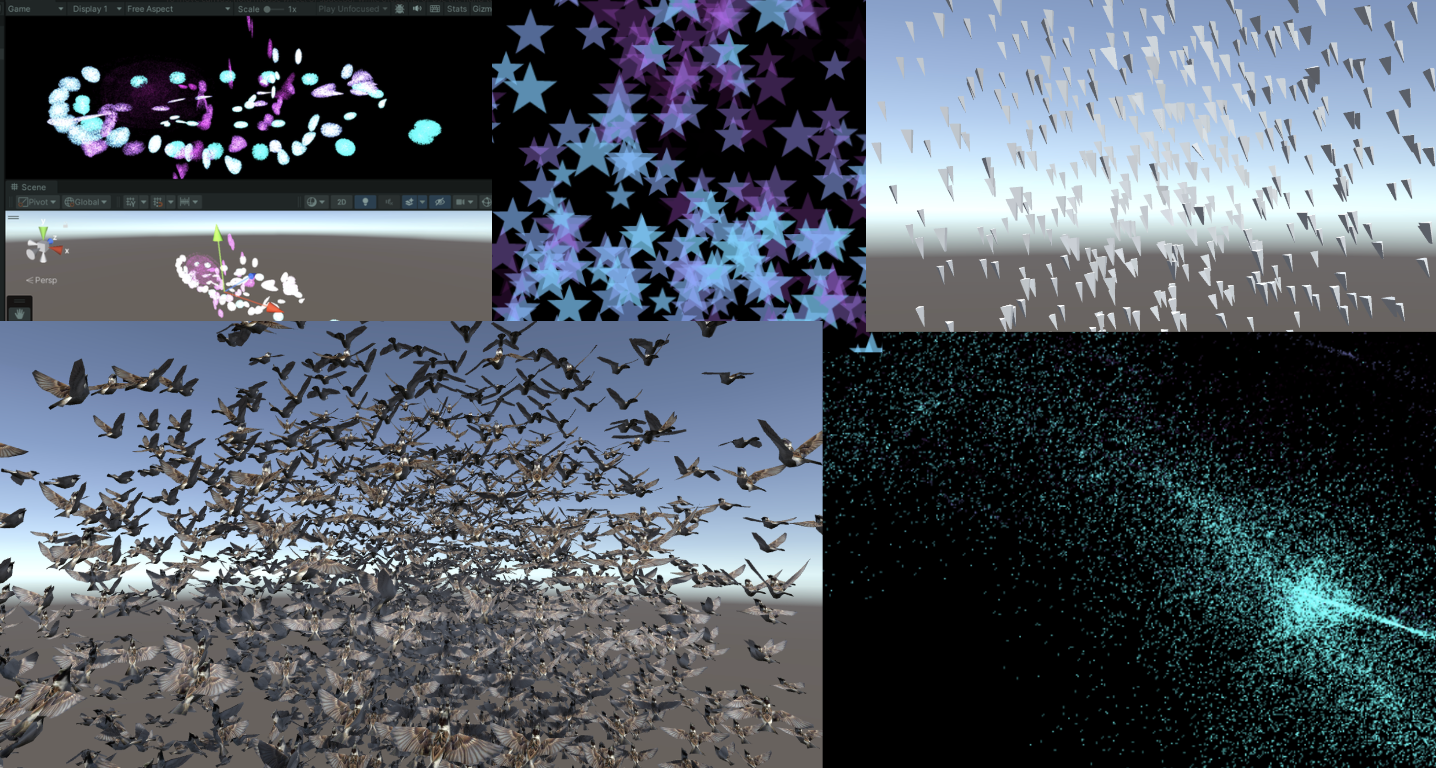

紧接着上一篇文章
remoooo:Compute Shader学习笔记(二)之 后处理效果
本章节使用Compute Shader生成粒子。学习如何使用DrawProcedural和DrawMeshInstancedIndirect,也就是GPU Instancing。
知识点总结:
Compute Shader除了可以同时处理大量的数据,还有一个关键的优势,就是Buffer存储在GPU中。因此可以将Compute Shader处理好的数据直接传递给与Material关联的Shader中,即Vertex/Fragment Shader。这里的关键就是,material也可以像Compute Shader一样SetBuffer(),直接从GPU的Buffer中访问数据!

使用Compute Shader来制作粒子系统可以充分体现Compute Shader的强大并行能力。
在渲染过程中,Vertex Shader会从Compute Buffer中读取每个粒子的位置和其他属性,并将它们转换为屏幕上的顶点。Fragment Shader则负责根据这些顶点的信息(如位置和颜色)来生成像素。通过Graphics.DrawProcedural方法,Unity可以直接渲染这些由Shader处理的顶点,无需预先定义的网格结构,也不依赖Mesh Renderer,这对于渲染大量粒子特别有效。
步骤也是非常简单,在 C# 中定义好粒子的信息(位置、速度与生命周期),初始化将数据传给Buffer,绑定Buffer到Compute Shader和Material。渲染阶段在OnRenderObject()里调用Graphics.DrawProceduralNow实现高效地渲染粒子。

新建一个场景,制作一个效果:百万粒子跟随鼠标绽放生命的粒子,如下:

写到这里,不禁让我思绪万千。粒子的生命周期很短暂,如同星火一般瞬间点燃,又如同流星一闪即逝。纵有千百磨难,我亦不过是亿万尘埃中的一粒,平凡且渺小。这些粒子,虽或许会在空间中随机漂浮(使用”Xorshift”算法计算粒子生成的位置),或许会拥有独一无二的色彩,但它们终究逃不出被程式预设的命运。这难道不正是我的人生写照吗?按部就班地上演着自己的角色,无法逃脱那无形的束缚。
“上帝已死!而我们这些杀死他的人,又怎能不感到最大的痛苦呢?” – 弗里德里希·尼采
尼采不仅宣告了宗教信仰的消逝,更指出了现代人面临的虚无感,即没有了传统的道德和宗教支柱,人们感到了前所未有的孤独和方向感的缺失。粒子在C#脚本中被定义、创造,按照特定规则运动和消亡,这与尼采所描述的现代人在宇宙中的状态颇有相似之处。虽然每个人都试图寻找自己的意义,但最终仍受限于更广泛的社会和宇宙规则。
生活中充满了各种不可避免的痛苦,反映了人类存在的固有虚无和孤独感。失恋、生离死别、工作失意以及即将编写的粒子死亡逻辑等等,都印证了尼采所表达的,生活中没有什么是永恒不变的。同一个Buffer中的粒子必然在未来某个时刻消失,这体现了尼采所描述的现代人的孤独感,个体可能会感受到前所未有的孤立无援,因此每个人都是孤独的战士,必须学会独自面对内心的龙卷风和外部世界的冷漠。
但是没关系,「夏天会周而复始,该相逢的人会再次相逢」。本文的粒子也会在结束后再次生成,以最好的状态拥抱属于它的Buffer。
Summer will come around again. People who meet will meet again.

当前版本代码,可以自己拷下来跑跑(都有注释):
废话就说到这,先看看 C# 脚本是咋写的。

老样子,先定义粒子的Buffer(结构体),并且初始化一下子,然后传给GPU,关键在于最后三行将Buffer绑定给shader的操作。下面省略号的代码没什么好讲的,都是常规操作,用注释一笔带过了。
struct Particle{
    public Vector3 position; // 粒子位置
    public Vector3 velocity; // 粒子速度
    public float life;       // 粒子生命周期
}
ComputeBuffer particleBuffer; // GPU 的 Buffer
...
// Init() 中
    // 初始化粒子数组
    Particle[] particleArray = new Particle[particleCount];
    for (int i = 0; i < particleCount; i++){
        // 生成随机位置和归一化
        ...
        // 设置粒子的初始位置和速度
        ...
        // 设置粒子的生命周期
        particleArray[i].life = Random.value * 5.0f + 1.0f;
    }
    // 创建并设置Compute Buffer
    ...
    // 查找Compute Shader中的kernel ID
    ...
    // 绑定Compute Buffer到shader
    shader.SetBuffer(kernelID, "particleBuffer", particleBuffer);
    material.SetBuffer("particleBuffer", particleBuffer);
    material.SetInt("_PointSize", pointSize);
关键的渲染阶段来了 OnRenderObject() 。material.SetPass 用于设置渲染材质通道。DrawProceduralNow 方法在不使用传统网格的情况下绘制几何体。MeshTopology.Points 指定了渲染的拓扑类型为点,GPU会把每个顶点作为一个点来处理,不会进行顶点之间的连线或面的形成。第二个参数 1 表示从第一个顶点开始绘制。particleCount 指定了要渲染的顶点数,这里是粒子的数量,即告诉GPU总共需要渲染多少个点。
void OnRenderObject()
{
    material.SetPass(0);
    Graphics.DrawProceduralNow(MeshTopology.Points, 1, particleCount);
}
获取当前鼠标位置方法。OnGUI()这个方法每一帧可能调用多次。z值设为摄像机的近裁剪面加上一个偏移量,这里加14是为了得到一个更合适视觉深度的世界坐标(也可以自行调整)。
void OnGUI()
{
    Vector3 p = new Vector3();
    Camera c = Camera.main;
    Event e = Event.current;
    Vector2 mousePos = new Vector2();
    // Get the mouse position from Event.
    // Note that the y position from Event is inverted.
    mousePos.x = e.mousePosition.x;
    mousePos.y = c.pixelHeight - e.mousePosition.y;
    p = c.ScreenToWorldPoint(new Vector3(mousePos.x, mousePos.y, c.nearClipPlane + 14));
    cursorPos.x = p.x;
    cursorPos.y = p.y;
}
上面已经将 ComputeBuffer particleBuffer; 传到了Compute Shader和Shader中。
先看看Compute Shader的数据结构。没什么特别的。
// 定义粒子数据结构
struct Particle
{
    float3 position;  // 粒子的位置
    float3 velocity;  // 粒子的速度
    float life;       // 粒子的剩余生命时间
};
// 用于存储和更新粒子数据的结构化缓冲区,可从GPU读写
RWStructuredBuffer<Particle> particleBuffer;
// 从CPU设置的变量
float deltaTime;       // 从上一帧到当前帧的时间差
float2 mousePosition;  // 当前鼠标位置
这里简单讲讲一个特别好用的随机数序列生成方法 xorshift 算法。一会将用来随机粒子的运动方向如上图,粒子会随机朝着三维的方向运动。
这个算法03年由George Marsaglia提出,优点在于运算速度极快,并且非常节约空间。即使是最简单的Xorshift实现,其伪随机数周期也是相当长的。
基本操作是位移(shift)和异或(xor)。算法的名字也由此而来。它的核心是维护一个非零的状态变量,通过对这个状态变量进行一系列的位移和异或操作来生成随机数。
// 用于生成随机数的状态变量
uint rng_state;
uint rand_xorshift() {
    // Xorshift algorithm from George Marsaglia's paper
    rng_state ^= (rng_state << 13);  // 将状态变量左移13位,然后与原状态进行异或
    rng_state ^= (rng_state >> 17);  // 将更新后的状态变量右移17位,再次进行异或
    rng_state ^= (rng_state << 5);   // 最后,将状态变量左移5位,进行最后一次异或
    return rng_state;                // 返回更新后的状态变量作为生成的随机数
}
基本Xorshift 算法的核心已在前面的解释中提到,不过不同的位移组合可以创建多种变体。原论文还提到了Xorshift128变体。使用128位的状态变量,通过四次不同的位移和异或操作更新状态。代码如下:

// c language Ver
uint32_t xorshift128(void) {
    static uint32_t x = 123456789;
    static uint32_t y = 362436069;
    static uint32_t z = 521288629;
    static uint32_t w = 88675123;
    uint32_t t = x ^ (x << 11);
    x = y; y = z; z = w;
    w = w ^ (w >> 19) ^ (t ^ (t >> 8));
    return w;
}
可以产生更长的周期和更好的统计性能。这个变体的周期接近 ,非常厉害。
总的来说,这个算法用在游戏开发完全足够了,只是不适合用在密码学等领域。
在Compute Shader中使用这个算法时,需要注意Xorshift算法生成的随机数范围时uint32的的范围,需要再做一个映射( [0, 2^32-1] 映射到 [0, 1]):
float tmp = (1.0 / 4294967296.0);  // 转换因子
rand_xorshift()) * tmp
而粒子运动方向是有符号的,因此只要在这个基础上减去0.5就好了。三个方向的随机运动:
float f0 = float(rand_xorshift()) * tmp - 0.5;
float f1 = float(rand_xorshift()) * tmp - 0.5;
float f2 = float(rand_xorshift()) * tmp - 0.5;
float3 normalF3 = normalize(float3(f0, f1, f2)) * 0.8f; // 缩放了运动方向
每一个Kernel需要完成的内容如下:
生成粒子,初始位置利用刚刚Xorshift得到的随机数,定义粒子的生命值,重置速度。
// 设置粒子的新位置和生命值
particleBuffer[id].position = float3(normalF3.x + mousePosition.x, normalF3.y + mousePosition.y, normalF3.z + 3.0);
particleBuffer[id].life = 4;  // 重置生命值
particleBuffer[id].velocity = float3(0,0,0);  // 重置速度
最后是Shader的基本数据结构:
struct Particle{
    float3 position;
    float3 velocity;
    float life;
};
struct v2f{
    float4 position : SV_POSITION;
    float4 color : COLOR;
    float life : LIFE;
    float size: PSIZE;
};
// particles' data
StructuredBuffer<Particle> particleBuffer;
然后在顶点着色器计算粒子的顶点色、顶点的Clip位置以及传输一个顶点大小的信息。
v2f vert(uint vertex_id : SV_VertexID, uint instance_id : SV_InstanceID){
    v2f o = (v2f)0;
    // Color
    float life = particleBuffer[instance_id].life;
    float lerpVal = life * 0.25f;
    o.color = fixed4(1.0f - lerpVal+0.1, lerpVal+0.1, 1.0f, lerpVal);
    // Position
    o.position = UnityObjectToClipPos(float4(particleBuffer[instance_id].position, 1.0f));
    o.size = _PointSize;
    return o;
}
片元着色器计算插值颜色。
float4 frag(v2f i) : COLOR{
    return i.color;
}
至此,就可以得到上面的效果。

上一节每一个粒子都只有一个点,没什么意思。现在把一个点变成一个Quad。在Unity中,没有Quad,只有两个三角形组成的假Quad。
开干,基于上面的代码。在 C# 中定义顶点,一个Quad的尺寸。
// struct
struct Vertex
{
    public Vector3 position;
    public Vector2 uv;
    public float life;
}
const int SIZE_VERTEX = 6 * sizeof(float);
public float quadSize = 0.1f; // Quad的尺寸
每一个粒子的的基础上,设置六个顶点的uv坐标,给顶点着色器用。并且按照Unity规定的顺序绘制。
index = i*6;
    //Triangle 1 - bottom-left, top-left, top-right
    vertexArray[index].uv.Set(0,0);
    vertexArray[index+1].uv.Set(0,1);
    vertexArray[index+2].uv.Set(1,1);
    //Triangle 2 - bottom-left, top-right, bottom-right
    vertexArray[index+3].uv.Set(0,0);
    vertexArray[index+4].uv.Set(1,1);
    vertexArray[index+5].uv.Set(1,0);
最后传递给Buffer。这里的 halfSize 目的是传给Compute Shader计算Quad的各个顶点位置用的。
vertexBuffer = new ComputeBuffer(numVertices, SIZE_VERTEX);
vertexBuffer.SetData(vertexArray);
shader.SetBuffer(kernelID, "vertexBuffer", vertexBuffer);
shader.SetFloat("halfSize", quadSize*0.5f);
material.SetBuffer("vertexBuffer", vertexBuffer);
渲染阶段把点改为三角形,有六个点。
void OnRenderObject()
{
    material.SetPass(0);
    Graphics.DrawProceduralNow(MeshTopology.Triangles, 6, numParticles);
}
在Shader中改一下设置,接收顶点数据。并且接收一张贴图用于显示。需要做alpha剔除。
_MainTex("Texture", 2D) = "white" {}
...
Tags{ "Queue"="Transparent" "RenderType"="Transparent" "IgnoreProjector"="True" }
LOD 200
Blend SrcAlpha OneMinusSrcAlpha
ZWrite Off
...
    struct Vertex{
        float3 position;
        float2 uv;
        float life;
    };
    StructuredBuffer<Vertex> vertexBuffer;
    sampler2D _MainTex;
    v2f vert(uint vertex_id : SV_VertexID, uint instance_id : SV_InstanceID)
    {
        v2f o = (v2f)0;
        int index = instance_id*6 + vertex_id;
        float lerpVal = vertexBuffer[index].life * 0.25f;
        o.color = fixed4(1.0f - lerpVal+0.1, lerpVal+0.1, 1.0f, lerpVal);
        o.position = UnityWorldToClipPos(float4(vertexBuffer[index].position, 1.0f));
        o.uv = vertexBuffer[index].uv;
        return o;
    }
    float4 frag(v2f i) : COLOR
    {
        fixed4 color = tex2D( _MainTex, i.uv ) * i.color;
        return color;
    }
在Compute Shader中,增加接收顶点数据,还有halfSize。
struct Vertex
{
    float3 position;
    float2 uv;
    float life;
};
RWStructuredBuffer<Vertex> vertexBuffer;
float halfSize;
计算每个Quad六个顶点的位置。

//Set the vertex buffer //
    int index = id.x * 6;
    //Triangle 1 - bottom-left, top-left, top-right
    vertexBuffer[index].position.x = p.position.x-halfSize;
    vertexBuffer[index].position.y = p.position.y-halfSize;
    vertexBuffer[index].position.z = p.position.z;
    vertexBuffer[index].life = p.life;
    vertexBuffer[index+1].position.x = p.position.x-halfSize;
    vertexBuffer[index+1].position.y = p.position.y+halfSize;
    vertexBuffer[index+1].position.z = p.position.z;
    vertexBuffer[index+1].life = p.life;
    vertexBuffer[index+2].position.x = p.position.x+halfSize;
    vertexBuffer[index+2].position.y = p.position.y+halfSize;
    vertexBuffer[index+2].position.z = p.position.z;
    vertexBuffer[index+2].life = p.life;
    //Triangle 2 - bottom-left, top-right, bottom-right  // //
    vertexBuffer[index+3].position.x = p.position.x-halfSize;
    vertexBuffer[index+3].position.y = p.position.y-halfSize;
    vertexBuffer[index+3].position.z = p.position.z;
    vertexBuffer[index+3].life = p.life;
    vertexBuffer[index+4].position.x = p.position.x+halfSize;
    vertexBuffer[index+4].position.y = p.position.y+halfSize;
    vertexBuffer[index+4].position.z = p.position.z;
    vertexBuffer[index+4].life = p.life;
    vertexBuffer[index+5].position.x = p.position.x+halfSize;
    vertexBuffer[index+5].position.y = p.position.y-halfSize;
    vertexBuffer[index+5].position.z = p.position.z;
    vertexBuffer[index+5].life = p.life;
大功告成。

当前版本代码:
下一节,将Mesh升级为预制体,并且尝试模拟鸟类飞行时的集群行为。

Flocking 是一种模拟自然界中鸟群、鱼群等动物集体运动行为的算法。核心是基于三个基本的行为规则,由Craig Reynolds在Sig 87提出,通常被称为“Boids”算法:


思考一下,上面三个规则,哪一个最难实现?
答:Separation。众所周知,计算物体间的碰撞是非常难以实现的。因为每个个体都需要与其他所有个体进行距离比较,这会导致算法的时间复杂度接近O(n^2),其中n是粒子的数量。例如,如果有1000个粒子,那么在每次迭代中可能需要进行将近500,000次的距离计算。在当年原论文作者在没有经过优化的原始算法(时间复杂度O(N^2))中渲染一帧(80只鸟)所需时间是95秒,渲染一个300帧的动画使用了将近9个小时。
一般来说,使用四叉树或者是格点哈希(Spatial Hashing)等空间划分方法可以优化计算。也可以维护一个近邻列表存储每个个体周边一定距离的个体。当然了,还可以使用Compute Shader硬算。

废话不多说,开干。
首先下载好预备的工程文件(如果没有事先准备):
然后添加到一个空GO中。

启动项目就可以看到一堆鸟。

下面是关于群体行为模拟的一些参数。
// 定义群体行为模拟的参数。
    public float rotationSpeed = 1f; // 旋转速度。
    public float boidSpeed = 1f; // Boid速度。
    public float neighbourDistance = 1f; // 邻近距离。
    public float boidSpeedVariation = 1f; // 速度变化。
    public GameObject boidPrefab; // Boid对象的预制体。
    public int boidsCount; // Boid的数量。
    public float spawnRadius; // Boid生成的半径。
    public Transform target; // 群体的移动目标。
除了Boid预制体boidPrefab和生成半径spawnRadius之外,其他都需要传给GPU。
为了方便,这一节先犯个蠢,只在GPU计算鸟的位置和方向,然后传回给CPU,做如下处理:
...
boidsBuffer.GetData(boidsArray);
// 更新每个鸟的位置与朝向
for (int i = 0; i < boidsArray.Length; i++){
    boids[i].transform.localPosition = boidsArray[i].position;
    if (!boidsArray[i].direction.Equals(Vector3.zero)){
        boids[i].transform.rotation = Quaternion.LookRotation(boidsArray[i].direction);
    }
}
Quaternion.LookRotation() 方法用于创建一个旋转,使对象面向指定的方向。
在Compute Shader中计算每个鸟的位置。
#pragma kernel CSMain
#define GROUP_SIZE 256
struct Boid{
    float3 position;
    float3 direction;
};
RWStructuredBuffer<Boid> boidsBuffer;
float time;
float deltaTime;
float rotationSpeed;
float boidSpeed;
float boidSpeedVariation;
float3 flockPosition;
float neighbourDistance;
int boidsCount;
[numthreads(GROUP_SIZE,1,1)]
void CSMain (uint3 id : SV_DispatchThreadID){ …// 接下文 }
先写对齐和聚合的逻辑,最终输出实际位置、方向给Buffer。
Boid boid = boidsBuffer[id.x];
    float3 separation = 0; // 分离
    float3 alignment = 0; // 对齐 - 方向
    float3 cohesion = flockPosition; // 聚合 - 位置
    uint nearbyCount = 1; // 自身算作周边的个体。
    for (int i=0; i<boidsCount; i++)
    {
        if(i!=(int)id.x) // 把自己排除
        {
            Boid temp = boidsBuffer[i];
            // 计算周围范围内的个体
            if(distance(boid.position, temp.position)< neighbourDistance){
                alignment += temp.direction;
                cohesion += temp.position;
                nearbyCount++;
            }
        }
    }
    float avg = 1.0 / nearbyCount;
    alignment *= avg;
    cohesion *= avg;
    cohesion = normalize(cohesion-boid.position);
    // 综合一个移动方向
    float3 direction = alignment + separation + cohesion;
    // 平滑转向和位置更新
    boid.direction = lerp(direction, normalize(boid.direction), 0.94);
    // deltaTime确保移动速度不会因帧率变化而改变。
    boid.position += boid.direction * boidSpeed * deltaTime;
    boidsBuffer[id.x] = boid;
这就是没有边界感(分离项)的下场,所有的个体都表现出相当亲密的关系,都重叠在一起了。

添加下面的代码。
if(distance(boid.position, temp.position)< neighbourDistance)
{
    float3 offset = boid.position - temp.position;
    float dist = length(offset);
    if(dist < neighbourDistance)
    {
        dist = max(dist, 0.000001);
        separation += offset * (1.0/dist - 1.0/neighbourDistance);
    }
    ...
1.0/dist 当Boid越靠近时,这个值越大,表示分离力度应当越大。1.0/neighbourDistance 是一个常数,基于定义的邻近距离。两者的差值表示实际的分离力应对距离的反应程度。如果两个Boid的距离正好是 neighbourDistance,这个值为零(没有分离力)。如果两个Boid距离小于 neighbourDistance,这个值为正,且距离越小,值越大。

当前代码:https://github.com/Remyuu/Unity-Compute-Shader-Learn/blob/L4_Flocking/Assets/Shaders/SimpleFlocking.compute
下一节将采用Instanced Mesh,提高性能。
首先回顾一下本章节的内容。「粒子你好」与「Quad粒子」的两个例子中,我们都运用了Instanced技术(Graphics.DrawProceduralNow()),将Compute Shader的计算好的粒子位置直接传递给VertexFrag着色器。

本节使用的DrawMeshInstancedIndirect 用于绘制大量几何体实例,实例都是相似的,只是位置、旋转或其他参数略有不同。相对于每帧都重新生成几何体并渲染的 DrawProceduralNow,DrawMeshInstancedIndirect 只需要一次性设置好实例的信息,然后 GPU 就可以根据这些信息一次性渲染所有实例。渲染草地、群体动物就用这个函数。

这个函数有很多参数,只用其中的一部分。

Graphics.DrawMeshInstancedIndirect(boidMesh, 0, boidMaterial, bounds, argsBuffer);这个 argsBuffer 是啥?这个参数用来告诉Unity,我们现在要渲染哪个Mesh、要渲染多少个!可以用一种特殊的Buffer作为参数给进去。
在初始化shader时候,创建一种特殊Buffer,其标注为 ComputeBufferType.IndirectArguments 。这种类型的缓冲区专门用于传递给 GPU,以便在 GPU 上执行间接绘制命令。这里的new ComputeBuffer 第一个参数是 1 ,表示一个args数组(一个数组有5个uint),不要理解错了。
ComputeBuffer argsBuffer;
...
argsBuffer = new ComputeBuffer(1, 5 * sizeof(uint), ComputeBufferType.IndirectArguments);
if (boidMesh != null)
{
    args[0] = (uint)boidMesh.GetIndexCount(0);
    args[1] = (uint)numOfBoids;
}
argsBuffer.SetData(args);
...
Graphics.DrawMeshInstancedIndirect(boidMesh, 0, boidMaterial, bounds, argsBuffer);
在上一章的基础上,个体的数据结构增加一个offset,在Compute Shader用于方向上的偏移。另外初始状态的方向用Slerp插值,70%保持原来的方向,30%随机。Slerp插值的结果是四元数,需要用四元数方法转换到欧拉角再传入构造函数。
public float noise_offset;
...
Quaternion rot = Quaternion.Slerp(transform.rotation, Random.rotation, 0.3f);
boidsArray[i] = new Boid(pos, rot.eulerAngles, offset);
将这个新的属性noise_offset传到Compute Shader后,计算范围是 [-1, 1] 的噪声值,应用到鸟的速度上。
float noise = clamp(noise1(time / 100.0 + boid.noise_offset), -1, 1) * 2.0 - 1.0;
float velocity = boidSpeed * (1.0 + noise * boidSpeedVariation);
然后稍微优化了一下算法。Compute Shader大体是没有区别的。
if (distance(boid_pos, boidsBuffer[i].position) < neighbourDistance)
{
    float3 tempBoid_position = boidsBuffer[i].position;
    float3 offset = boid.position - tempBoid_position;
    float dist = length(offset);
    if (dist<neighbourDistance){
        dist = max(dist, 0.000001);//Avoid division by zero
        separation += offset * (1.0/dist - 1.0/neighbourDistance);
    }
    alignment += boidsBuffer[i].direction;
    cohesion += tempBoid_position;
    nearbyCount += 1;
}
最大的不同在于Shader上。本节使用Surface Shader取代Frag。这个东西其实就是一个包装好的vertex and fragment shader。Unity已经完成了光照、阴影等一系列繁琐的工作。你依旧可以指定一个Vert。
写Shader制作材质的时候,需要对Instanced的物体做特别处理。因为普通的渲染对象,他们的位置、旋转和其他属性在Unity中是静态的。而对于当前要构建的实例化对象,其位置、旋转等参数时刻在变化,因此,在渲染管线中需要通过特殊的机制来动态设置每个实例化对象的位置和参数。当前的方法基于程序的实例化技术,可以一次性渲染所有的实例化对象,而不需要逐个绘制。也就是一次性批量渲染。
着色器应用instanced技术方法。实例化阶段是在vert之前执行。这样每个实例化的对象都有单独的旋转、位移和缩放等矩阵。
现在需要为每个实例化对象创建属于他们的旋转矩阵。从Buffer中我们拿到了Compute Shader计算后的鸟的基本信息(上一节中,该数据传回了CPU,这里直接传给Shader做实例化):

Shader里将Buffer传来的数据结构、相关操作用下面的宏包裹起来。
// .shader
#ifdef UNITY_PROCEDURAL_INSTANCING_ENABLED
struct Boid
{
    float3 position;
    float3 direction;
    float noise_offset;
};
StructuredBuffer<Boid> boidsBuffer;
#endif
由于我只在 C# 的 DrawMeshInstancedIndirect 的args[1]指定了需要实例化的数量(鸟的数量,也是Buffer的大小),因此直接使用unity_InstanceID索引访问Buffer就好了。
#pragma instancing_options procedural:setup
void setup()
{
    #ifdef UNITY_PROCEDURAL_INSTANCING_ENABLED
        _BoidPosition = boidsBuffer[unity_InstanceID].position;
        _Matrix = create_matrix(boidsBuffer[unity_InstanceID].position, boidsBuffer[unity_InstanceID].direction, float3(0.0, 1.0, 0.0));
    #endif
}这里的空间变换矩阵的计算涉及到Homogeneous Coordinates,可以去复习一下GAMES101的课程。点是(x,y,z,1),坐标是(x,y,z,0)。
如果使用仿射变换(Affine Transformations),代码是这样的:
void setup()
{
    #ifdef UNITY_PROCEDURAL_INSTANCING_ENABLED
    _BoidPosition = boidsBuffer[unity_InstanceID].position;
    _LookAtMatrix = look_at_matrix(boidsBuffer[unity_InstanceID].direction, float3(0.0, 1.0, 0.0));
    #endif
}
 void vert(inout appdata_full v, out Input data)
{
    UNITY_INITIALIZE_OUTPUT(Input, data);
    #ifdef UNITY_PROCEDURAL_INSTANCING_ENABLED
    v.vertex = mul(_LookAtMatrix, v.vertex);
    v.vertex.xyz += _BoidPosition;
    #endif
}
不够优雅,我们直接使用一个齐次坐标(Homogeneous Coordinates)。一个矩阵搞掂旋转平移缩放!
void setup()
{
    #ifdef UNITY_PROCEDURAL_INSTANCING_ENABLED
    _BoidPosition = boidsBuffer[unity_InstanceID].position;
    _Matrix = create_matrix(boidsBuffer[unity_InstanceID].position, boidsBuffer[unity_InstanceID].direction, float3(0.0, 1.0, 0.0));
    #endif
}
 void vert(inout appdata_full v, out Input data)
{
    UNITY_INITIALIZE_OUTPUT(Input, data);
    #ifdef UNITY_PROCEDURAL_INSTANCING_ENABLED
    v.vertex = mul(_Matrix, v.vertex);
    #endif
}
至此,就大功告成了!当前的帧率比上一节提升了将近一倍。


当前版本代码:

本节要做的是,使用Animator组件,在实例化物体之前,将各个关键帧的Mesh抓取到Buffer当中。通过选取不同索引,得到不同姿势的Mesh。具体的骨骼动画制作不在本文讨论范围。
只需要在上一章的基础上修改代码,添加Animator等逻辑。我已经在下面写了注释,可以看看。
并且个体的数据结构有所更新:
struct Boid{
    float3 position;
    float3 direction;
    float noise_offset;
    float speed; // 暂时没啥用
    float frame; // 表示动画中的当前帧索引
    float3 padding; // 确保数据对齐
};
详细说说这里的对齐。一个数据结构中,数据的大小最好是16字节的整数倍。
如果没有Padding,大小是36字节,不是常见的对齐大小。加上Padding,对齐到48字节,完美!
private SkinnedMeshRenderer boidSMR; // 用于引用包含蒙皮网格的SkinnedMeshRenderer组件。
private Animator animator;
public AnimationClip animationClip; // 具体的动画剪辑,通常用于计算动画相关的参数。
private int numOfFrames; // 动画中的帧数,用于确定在GPU缓冲区中存储多少帧数据。
public float boidFrameSpeed = 10f; // 控制动画播放的速度。
MaterialPropertyBlock props; // 在不创建新材料实例的情况下传递参数给着色器。这意味着可以改变实例的材质属性(如颜色、光照系数等),而不会影响到使用相同材料的其他对象。
Mesh boidMesh; // 存储从SkinnedMeshRenderer烘焙出的网格数据。
...
void Start(){ // 这里首先初始化Boid数据,然后调用GenerateSkinnedAnimationForGPUBuffer来准备动画数据,最后调用InitShader来设置渲染所需的Shader参数。
    ...
    // This property block is used only for avoiding an instancing bug.
    props = new MaterialPropertyBlock();
    props.SetFloat("_UniqueID", Random.value);
    ...
    InitBoids();
    GenerateSkinnedAnimationForGPUBuffer();
    InitShader();
}
void InitShader(){ // 此方法配置Shader和材料属性,确保动画播放可以根据实例的不同阶段正确显示。frameInterpolation的启用或禁用决定了是否在动画帧之间进行插值,以获得更平滑的动画效果。
    ...
    if (boidMesh)//Set by the GenerateSkinnedAnimationForGPUBuffer
    ...
    shader.SetFloat("boidFrameSpeed", boidFrameSpeed);
    shader.SetInt("numOfFrames", numOfFrames);
    boidMaterial.SetInt("numOfFrames", numOfFrames);
    if (frameInterpolation && !boidMaterial.IsKeywordEnabled("FRAME_INTERPOLATION"))
    boidMaterial.EnableKeyword("FRAME_INTERPOLATION");
    if (!frameInterpolation && boidMaterial.IsKeywordEnabled("FRAME_INTERPOLATION"))
    boidMaterial.DisableKeyword("FRAME_INTERPOLATION");
}
void Update(){
    ...
    // 后面两个参数:
        // 1. 0: 参数缓冲区的偏移量,用于指定从哪里开始读取参数。
        // 2. props: 前面创建的 MaterialPropertyBlock,包含所有实例共享的属性。
    Graphics.DrawMeshInstancedIndirect( boidMesh, 0, boidMaterial, bounds, argsBuffer, 0, props);
}
void OnDestroy(){
    ...
    if (vertexAnimationBuffer != null) vertexAnimationBuffer.Release();
}
private void GenerateSkinnedAnimationForGPUBuffer()
{
    ... // 接下文
}
为了给Shader在不同的时间提供不同姿势的Mesh,因此在 GenerateSkinnedAnimationForGPUBuffer() 函数中,从 Animator 和 SkinnedMeshRenderer 中提取每一帧的网格顶点数据,然后将这些数据存储到GPU的 ComputeBuffer 中,以便在实例化渲染时使用。
通过GetCurrentAnimatorStateInfo获取当前动画层的状态信息,用于后续控制动画的精确播放。
numOfFrames 使用最接近动画长度和帧率乘积的二次幂来确定,可以优化GPU的内存访问。
然后创建一个ComputeBuffer来存储所有帧的所有顶点数据。vertexAnimationBuffer
在for循环中,烘焙所有动画帧。具体做法是,在每个sampleTime时间点播放并立即更新,然后烘焙当前动画帧的网格到bakedMesh中。并且提取刚刚烘焙好的Mesh顶点,更新到数组 vertexAnimationData 中,最后上传至GPU,结束。
// ...接上文
boidSMR = boidObject.GetComponentInChildren<SkinnedMeshRenderer>();
boidMesh = boidSMR.sharedMesh;
animator = boidObject.GetComponentInChildren<Animator>();
int iLayer = 0;
AnimatorStateInfo aniStateInfo = animator.GetCurrentAnimatorStateInfo(iLayer);
Mesh bakedMesh = new Mesh();
float sampleTime = 0;
float perFrameTime = 0;
numOfFrames = Mathf.ClosestPowerOfTwo((int)(animationClip.frameRate * animationClip.length));
perFrameTime = animationClip.length / numOfFrames;
var vertexCount = boidSMR.sharedMesh.vertexCount;
vertexAnimationBuffer = new ComputeBuffer(vertexCount * numOfFrames, 16);
Vector4[] vertexAnimationData = new Vector4[vertexCount * numOfFrames];
for (int i = 0; i < numOfFrames; i++)
{
    animator.Play(aniStateInfo.shortNameHash, iLayer, sampleTime);
    animator.Update(0f);
    boidSMR.BakeMesh(bakedMesh);
    for(int j = 0; j < vertexCount; j++)
    {
        Vector4 vertex = bakedMesh.vertices[j];
        vertex.w = 1;
        vertexAnimationData[(j * numOfFrames) +  i] = vertex;
    }
    sampleTime += perFrameTime;
}
vertexAnimationBuffer.SetData(vertexAnimationData);
boidMaterial.SetBuffer("vertexAnimation", vertexAnimationBuffer);
boidObject.SetActive(false);
在Compute Shader中,维护每一个个体数据结构中储存的帧变量。
boid.frame = boid.frame + velocity * deltaTime * boidFrameSpeed;
if (boid.frame >= numOfFrames) boid.frame -= numOfFrames;
在Shader中lerp不同帧的动画。左边是没有帧插值的,右边是插值后的,效果非常显著。

好的标题可以获得更多的推荐及关注者
void vert(inout appdata_custom v)
{
    #ifdef UNITY_PROCEDURAL_INSTANCING_ENABLED
        #ifdef FRAME_INTERPOLATION
            v.vertex = lerp(vertexAnimation[v.id * numOfFrames + _CurrentFrame], vertexAnimation[v.id * numOfFrames + _NextFrame], _FrameInterpolation);
        #else
            v.vertex = vertexAnimation[v.id * numOfFrames + _CurrentFrame];
        #endif
        v.vertex = mul(_Matrix, v.vertex);
    #endif
}
void setup()
{
    #ifdef UNITY_PROCEDURAL_INSTANCING_ENABLED
        _Matrix = create_matrix(boidsBuffer[unity_InstanceID].position, boidsBuffer[unity_InstanceID].direction, float3(0.0, 1.0, 0.0));
        _CurrentFrame = boidsBuffer[unity_InstanceID].frame;
        #ifdef FRAME_INTERPOLATION
            _NextFrame = _CurrentFrame + 1;
            if (_NextFrame >= numOfFrames) _NextFrame = 0;
            _FrameInterpolation = frac(boidsBuffer[unity_InstanceID].frame);
        #endif
    #endif
}
非常不容易,终于完整了。

完整工程链接:https://github.com/Remyuu/Unity-Compute-Shader-Learn/tree/L4_Skinned/Assets/Scripts
When rendering points which gives the best answer?

What are the three key steps in flocking?

When creating an arguments buffer for DrawMeshInstancedIndirect, how many uints are required?

We created the wing flapping by using a skinned mesh shader. True or False.
In a shader used by DrawMeshInstancedIndirect, which variable name gives the correct index for the instance?