标签 :入门/Shader/计算着色器/GPU优化

前言
Compute Shader比较复杂,需要具备一定的编程知识、图形学知识以及GPU相关的硬件知识才能较好的掌握。学习笔记分为四个部分:
- 初步认识Compute Shader,实现一些简单的效果
- 画圆、星球轨道、噪声图、操控Mesh等等
- 后处理、粒子系统
- 物理模拟、绘制草地
- 流体模拟
主要参考资料如下:
- https://www.udemy.com/course/compute-shaders/?couponCode=LEADERSALE24A
- https://catlikecoding.com/unity/tutorials/basics/compute-shaders/
- https://medium.com/ericzhan-publication/shader筆記-初探compute-shader-9efeebd579c1
- https://docs.unity3d.com/Manual/class-ComputeShader.html
- https://docs.unity3d.com/ScriptReference/ComputeShader.html
- https://learn.microsoft.com/en-us/windows/win32/api/D3D11/nf-d3d11-id3d11devicecontext-dispatch
- lygyue:Compute Shader(很有意思)
- https://medium.com/@sengallery/unity-compute-shader-基礎認識-5a99df53cea1
- https://kylehalladay.com/blog/tutorial/2014/06/27/Compute-Shaders-Are-Nifty.html(太老,已经过时)
- http://www.sunshine2k.de/coding/java/Bresenham/RasterisingLinesCircles.pdf
- 王江荣:【Unity】Compute Shader的基础介绍与使用
- …未完待续
L1 介绍Compute Shader
1. 初识Compute Shader
简单的说,可以通过Compute Shader,计算出一个材质,然后通过Renderer显示出来。需要注意,Compute Shader不仅仅可以做这些。


可以把下面两份代码拷下来测试一下。
using System.Collections;
using System.Collections.Generic;
using UnityEngine;

public class AssignTexture : MonoBehaviour
{
    // ComputeShader 用于在 GPU 上执行计算任务
    public ComputeShader shader;

    // 纹理分辨率
    public int texResolution = 256;

    // 渲染器组件
    private Renderer rend;
    // 渲染纹理
    private RenderTexture outputTexture;
    // 计算着色器内核句柄
    private int kernelHandle;

    // Start 在脚本启用时被调用一次
    void Start()
    {
        // 创建一个新的渲染纹理,指定宽度、高度和位深度(此处位深度为0)
        outputTexture = new RenderTexture(texResolution, texResolution, 0);
        // 允许随机写入
        outputTexture.enableRandomWrite = true;
        // 创建渲染纹理实例
        outputTexture.Create();

        // 获取当前对象的渲染器组件
        rend = GetComponent<Renderer>();
        // 启用渲染器
        rend.enabled = true;

        InitShader();
    }

    private void InitShader()
    {
        // 查找计算着色器内核 "CSMain" 的句柄
        kernelHandle = shader.FindKernel("CSMain");

        // 设置计算着色器中使用的纹理
        shader.SetTexture(kernelHandle, "Result", outputTexture);

        // 将渲染纹理设置为材质的主纹理
        rend.material.SetTexture("_MainTex", outputTexture);

        // 调度计算着色器的执行,传入计算组的大小
        // 这里假设每个工作组是 16x16
        // 简单的说就是,要分配多少个组,才能完成计算,目前只分了xy的各一半,因此只渲染了1/4的画面。
        DispatchShader(texResolution / 16, texResolution / 16);
    }

    private void DispatchShader(int x, int y)
    {
        // 调度计算着色器的执行
        // x 和 y 表示计算组的数量,1 表示 z 方向上的计算组数量(这里只有一个)
        shader.Dispatch(kernelHandle, x, y, 1);
    }

    void Update()
    {
        // 每帧检查是否有键盘输入(按键 U 被松开)
        if (Input.GetKeyUp(KeyCode.U))
        {
            // 如果按键 U 被松开,则重新调度计算着色器
            DispatchShader(texResolution / 8, texResolution / 8);
        }
    }
}
Unity默认的Compute Shader:
// Each #kernel tells which function to compile; you can have many kernels
#pragma kernel CSMain

// Create a RenderTexture with enableRandomWrite flag and set it
// with cs.SetTexture
RWTexture2D<float4> Result;

[numthreads(8,8,1)]
void CSMain (uint3 id : SV_DispatchThreadID) {
  // TODO: insert actual code here! Result[id.xy] = float4(id.x & id.y, (id.x & 15)/15.0, (id.y & 15)/15.0, 0.0);
}
在这个示例中,我们可以看到左下角四分之一的区域绘制上了一种名为Sierpinski网的分形结构,这个无关紧要,Unity官方觉得这个图形很有代表性,就把它当作默认代码了。
具体讲一下Compute Shader的代码, C# 的代码看注释即可。
#pragma kernel CSMain 这行代码指示了Compute Shader的入口。CSMain名字随便改。
RWTexture2D Result 这行代码是一个可读写的二维纹理。R代表Read,W代表Write。
着重看这一行代码:
[numthreads(8,8,1)]在Compute Shader文件中,这行代码规定了一个线程组的大小,比如这个8 * 8 * 1的线程组中,一共有64个线程。每一个线程计算一个单位的像素(RWTexture)。
而在上面的 C# 文件中,我们用 shader.Dispatch 指定线程组的数量。


接下来提一个问题,如果当前线程组指定为 881 ,那么我们需要多少个线程组才能渲染完 res*res 大小的RWTexture呢?
答案是:res/8 个。而我们代码目前只调用了 res/16 个,因此只渲染了左下角的1/4的区域。
除此之外,入口函数传入的参数也值得一说。uint3 id : SV_DispatchThreadID 这个id表示当前线程的唯一标识符。
2. 四分图案
学会走之前,先学会爬。首先在 C# 中指定需要执行的任务(Kernel)。

目前我们写死了,现在我们暴露一个参数,表示可以执行渲染不同的任务。
public string kernelName = "CSMain";
...
kernelHandle = shader.FindKernel(kernelName);
这样,就可以在Inspector中随意修改了。

但是,光上盘子可不行,得上菜啊。我们在Compute Shader中做菜。
先设置几个菜单。
#pragma kernel CSMain // 刚刚我们已经声明好了
#pragma kernel SolidRed // 定义一个新的菜,并且在下面写出来就好了
... // 可以写很多
[numthreads(8,8,1)]
void CSMain (uint3 id : SV_DispatchThreadID){ ... }
[numthreads(8,8,1)]
void SolidRed (uint3 id : SV_DispatchThreadID){
 Result[id.xy] = float4(1,0,0,0);
}
在Inspector中修改对应的名字,就可以启用不同的Kernel。

如果我想传数据给Compute Shader咋办?比方说,给Compute Shader传一个材质的分辨率。
shader.SetInt("texResolution", texResolution);

并且在Compute Shader里,也要声明好。

思考一个问题,怎么实现下面的效果?

[numthreads(8,8,1)]
void SplitScreen (uint3 id : SV_DispatchThreadID)
{
    int halfRes = texResolution >> 1;
    Result[id.xy] = float4(step(halfRes, id.x),step(halfRes, id.y),0,1);
}
解释一下,step 函数其实就是:
step(edge, x){
    return x>=edge ? 1 : 0;
}
(uint)res >> 1 意思就是res的位往右边移动一位。相当于除2(二进制的内容)。
这个计算方法就只是简单的依赖当前的线程id。
位于左下角的线程永远输出黑色。因为step返回永远都是0。
而左下半边的线程, id.x > halfRes ,因此在红通道返回1。
以此类推,非常简单。如果你不信服,可以具体算一下,可以帮助理解线程id、线程组和线程组组的关系。


3. 画圆
原理听上去很简单,判断 (id.x, id.y) 是否在圆内,是则输出1,否则0。动手试试吧。

float inCircle( float2 pt, float radius ){
    return ( length(pt)<radius ) ? 1.0 : 0.0;
}

[numthreads(8,8,1)]
void Circle (uint3 id : SV_DispatchThreadID)
{
    int halfRes = texResolution >> 1;
    int isInside = inCircle((float2)((int2)id.xy-halfRes), (float)(halfRes>>1));
    Result[id.xy] = float4(0.0,isInside ,0,1);
}
4. 总结/小测试
如果输出是 256 为边长的RWTexture,哪个答案会产生完整的红色的纹理?
RWTexture2D<float4> output;

[numthreads(16,16,1)]
void CSMain (uint3 id : SV_DispatchThreadID)
{
     output[id.xy] = float4(1.0, 0.0, 0.0, 1.0);
}
哪个答案将在纹理输出的左侧给出红色,右侧给出黄色?

L2 开始了
1. 传递值给GPU

废话不多说,先画一个圆。两份初始代码在这里。
PassData.cs: https://pastebin.com/PMf4SicK
PassData.compute: https://pastebin.com/WtfUmhk2
大体结构和上文的没有变化。可以看到最终调用了一个drawCircle函数来画圆。
[numthreads(1,1,1)]
void Circles (uint3 id : SV_DispatchThreadID)
{
    int2 centre = (texResolution >> 1);
    int radius = 80;
    drawCircle( centre, radius );
}
这里使用的画圆方法是非常经典的光栅化绘制方法,对数学原理感兴趣的可以看 http://www.sunshine2k.de/coding/java/Bresenham/RasterisingLinesCircles.pdf 。大概思路是利用一种对称的思想生成的。
不同的是,这里我们使用指定 (1,1,1) 为一个线程组的大小。在CPU端调用CS:
private void DispatchKernel(int count)
{
    shader.Dispatch(circlesHandle, count, 1, 1);
}
void Update()
{
    DispatchKernel(1);
}
问题来了,请问一个线程执行了多少次?
答:只执行了一次。因为一个线程组只有 111=1 个线程,并且CPU端只调用了 111=1 个线程组来计算。因此只用了一个线程完成了一个圆的绘制。也就是说,一个线程可以一次绘制一整个RWTexture,也不是之前那样,一个线程绘制一个pixel。
这也说明了Compute Shader和Fragment Shader是有本质的区别的。片元着色器只是计算单个像素的颜色,而Compute Shader可以执行或多或少任意的操作!

回到Unity,想绘制好看的圆,就需要轮廓颜色、填充颜色。将这两个参数传递到CS中。
float4 clearColor;
float4 circleColor;
并且增加颜色填充Kernel,并修改Circles内核。如果有多个内核同时访问一个RWTexture的时候,可以添加上 shared 关键词。
#pragma kernel Circles
#pragma kernel Clear
    ...
shared RWTexture2D<float4> Result;
    ...
[numthreads(32,1,1)]
void Circles (uint3 id : SV_DispatchThreadID)
{
    // int2 centre = (texResolution >> 1);
    int2 centre = (int2)(random2((float)id.x) * (float)texResolution);
    int radius = (int)(random((float)id.x) * 30);
    drawCircle( centre, radius );
}

[numthreads(8,8,1)]
void Clear (uint3 id : SV_DispatchThreadID)
{
    Result[id.xy] = clearColor;
}
在CPU端获取Clear内核,传入数据。
private int circlesHandle;
private int clearHandle;
    ...
shader.SetVector( "clearColor", clearColor);
shader.SetVector( "circleColor", circleColor);
    ...
private void DispatchKernels(int count)
{
    shader.Dispatch(clearHandle, texResolution/8, texResolution/8, 1);
    shader.Dispatch(circlesHandle, count, 1, 1);
}
void Update()
{
    DispatchKernels(1); // 现在画面有32个圆圆
}
一个问题,如果代码改为:DispatchKernels(10) ,画面会有多少个圆?
答:320个。一开始Dispatch为 111=1 时,一个线程组有 3211=32 个线程,每个线程画一个圆。小学数学。
接下来,加入 _Time 变量,让圆圆随着时间变化。由于Compute Shader内部貌似没有_time这样的变量,所以只能由CPU传入。
CPU端,注意,实时更新的变量需要在每次Dispatch前更新(outputTexture不需要,因为这outputTexture指向的实际上是GPU纹理的引用!):
private void DispatchKernels(int count)
{
    shader.Dispatch(clearHandle, texResolution/8, texResolution/8, 1);
    shader.SetFloat( "time", Time.time);
    shader.Dispatch(circlesHandle, count, 1, 1);
}
Compute Shader:
float time;
...
void Circles (uint3 id : SV_DispatchThreadID){
    ...
    int2 centre = (int2)(random2((float)id.x + time) * (float)texResolution);
    ...
}
当前版本代码:
- Compute Shader:https://github.com/Remyuu/Unity-Compute-Shader-Learn/blob/L2_Circle_Time/Assets/Shaders/PassData.compute
- CPU:https://github.com/Remyuu/Unity-Compute-Shader-Learn/blob/L2_Circle_Time/Assets/Scripts/PassData.cs
但是现在的圆非常混乱,下一步就需要利用Buffer让圆圆看起来更有规律。

同时不需要担心多个线程尝试同时写入同一个内存位置(比如 RWTexture),可能会出现竞争条件(race condition)。当前的API都会很好的处理这个问题。
2. 利用Buffer传递数据给GPU
目前为止,我们学习了如何从CPU传送一些简单的数据给GPU。如何传递自定义的结构体呢?

我们可以使用Buffer作为媒介,其中Buffer当然是存在GPU当中的,CPU端(C#)只存储其引用。。首先,在CPU声明一个结构体,然后声明CPU端的引用和GPU端的引用。
struct Circle
{
    public Vector2 origin;
    public Vector2 velocity;
    public float radius;
}
    Circle[] circleData;  // 在CPU上
    ComputeBuffer buffer; // 在GPU上
获取一个线程组的大小信息,可以这样,下面代码只获取了circlesHandles线程组的x方向上的线程数量,yz都不要了(因为假设线程组yz都是1)。并且乘上分配的线程组数量,就可以得到总的线程数量。
uint threadGroupSizeX;
shader.GetKernelThreadGroupSizes(circlesHandle, out threadGroupSizeX, out _, out _);
int total = (int)threadGroupSizeX * count;
现在把需要传给GPU的数据准备好。这里创建了线程数个圆形,circleData[threadNums]。
circleData = new Circle[total];
float speed = 100;
float halfSpeed = speed * 0.5f;
float minRadius = 10.0f;
float maxRadius = 30.0f;
float radiusRange = maxRadius - minRadius;
for(int i=0; i<total; i++)
{
    Circle circle = circleData[i];
    circle.origin.x = Random.value * texResolution;
    circle.origin.y = Random.value * texResolution;
    circle.velocity.x = (Random.value * speed) - halfSpeed;
    circle.velocity.y = (Random.value * speed) - halfSpeed;
    circle.radius = Random.value * radiusRange + minRadius;
    circleData[i] = circle;
}
然后在Compute Shader上接受这个Buffer。声明一个一模一样的结构体(Vector2和Float2是一样的),然后创建一个Buffer的引用。
// Compute Shader
struct circle
{
    float2 origin;
    float2 velocity;
    float radius;
};
StructuredBuffer<circle> circlesBuffer;
注意,这里使用的StructureBuffer是只读的,区别于下一节提到的RWStructureBuffer。
回到CPU端,将刚才准备好的CPU数据通过Buffer发送给GPU。首先明确我们申请的Buffer大小,也就是我们要传多大的东西给GPU。这里一份圆形的数据有两个 float2 的变量和一个 float 的变量,一个float是4bytes(不同平台可能不同,你可以用 sizeof(float) 加以判断),并且有 circleData.Length 份圆数据需要传递。circleData.Length表示缓冲区需要存储多少个圆形对象,而stride定义了每个对象的数据占用多少字节。开辟了这么大的空间,接下来使用SetData()将数据填充到缓冲区,也就是这一步,将数据传递给了GPU。最后将数据所在的GPU引用绑定到Compute Shader指定的Kernel。
int stride = (2 + 2 + 1) * 4; //2 floats origin, 2 floats velocity, 1 float radius - 4 bytes per float
buffer = new ComputeBuffer(circleData.Length, stride);
buffer.SetData(circleData);
shader.SetBuffer(circlesHandle, "circlesBuffer", buffer);
目前为止,我们已经将CPU准备好的一些数据,通过Buffer传递给了GPU。

OK,现在把好不容易传到GPU的数据利用起来。
[numthreads(32,1,1)]
void Circles (uint3 id : SV_DispatchThreadID)
{
    int2 centre = (int2)(circlesBuffer[id.x].origin + circlesBuffer[id.x].velocity * time);
    while (centre.x>texResolution) centre.x -= texResolution;
    while (centre.x<0) centre.x += texResolution;
    while (centre.y>texResolution) centre.y -= texResolution;
    while (centre.y<0) centre.y += texResolution;
    uint radius = (int)circlesBuffer[id.x].radius;
    drawCircle( centre, radius );
}
就可以看到,现在的圆圆是连续运动的。因为我们Buffer存储了id.x为索引的圆在上一帧的位置以及这个圆的运动状态。

总结一下,这一节学会了如何在CPU端自定义一个结构体(数据结构),并且通过Buffer传递给GPU,在GPU上对数据进行处理。
下一节,我们学习如何从GPU获取数据返回给CPU。
- 当前版本代码:
- Compute Shader:https://github.com/Remyuu/Unity-Compute-Shader-Learn/blob/L2_Using_Buffer/Assets/Shaders/BufferJoy.compute
- CPU:https://github.com/Remyuu/Unity-Compute-Shader-Learn/blob/L2_Using_Buffer/Assets/Scripts/BufferJoy.cs
3. 从GPU取得数据
还是老样子,创建一个Buffer,用于把数据从GPU传回给CPU。并且在CPU这边定义一个数组,用于接受数据。然后创建好缓冲区、绑定到着色器上,最后在CPU上创建好准备接受GPU数据的变量。
ComputeBuffer resultBuffer; // Buffer
Vector3[] output;           // CPU接受
...
    //buffer on the gpu in the ram
    resultBuffer = new ComputeBuffer(starCount, sizeof(float) * 3);
    shader.SetBuffer(kernelHandle, "Result", resultBuffer);
    output = new Vector3[starCount];
在Compute Shader中也接受这样一个Buffer。这里的Buffer是可读写的,也就是说这个Buffer可以被Compute Shader修改。上一节中,Compute Shader只需要读取Buffer,因此 StructuredBuffer 足矣。这里我们需要使用RW。
RWStructuredBuffer<float3> Result;接下来,在Dispatch后面用 GetData 接收数据即可。
shader.Dispatch(kernelHandle, groupSizeX, 1, 1);
resultBuffer.GetData(output);
思路就是这么简单。现在我们尝试制作一大堆围绕球心运动的星星场景。
将计算星星坐标的任务放到GPU上完成,最终获取计算好的各个星星的位置数据,在 C# 中实例化物体。
Compute Shader中,每一个线程计算一个星星的位置,然后输出到Buffer当中。
[numthreads(64,1,1)]
void OrbitingStars (uint3 id : SV_DispatchThreadID)
{
    float3 sinDir = normalize(random3(id.x) - 0.5);
    float3 vec = normalize(random3(id.x + 7.1393) - 0.5);
    float3 cosDir = normalize(cross(sinDir, vec));
    float scaledTime = time * 0.5 + random(id.x) * 712.131234;
    float3 pos = sinDir * sin(scaledTime) + cosDir * cos(scaledTime);
    Result[id.x] = pos * 2;
}
在CPU端通过 GetData 得到计算结果,时刻修改对应事先实例化好的GameObject的Pos。
void Update()
{
    shader.SetFloat("time", Time.time);
    shader.Dispatch(kernelHandle, groupSizeX, 1, 1);
    resultBuffer.GetData(output);
    for (int i = 0; i < stars.Length; i++)
        stars[i].localPosition = output[i];
}
当前版本代码:
- Compute Shader:https://github.com/Remyuu/Unity-Compute-Shader-Learn/blob/L2_GetData_From_Buffer/Assets/Shaders/OrbitingStars.compute
- CPU:https://github.com/Remyuu/Unity-Compute-Shader-Learn/blob/L2_GetData_From_Buffer/Assets/Scripts/OrbitingStars.cs
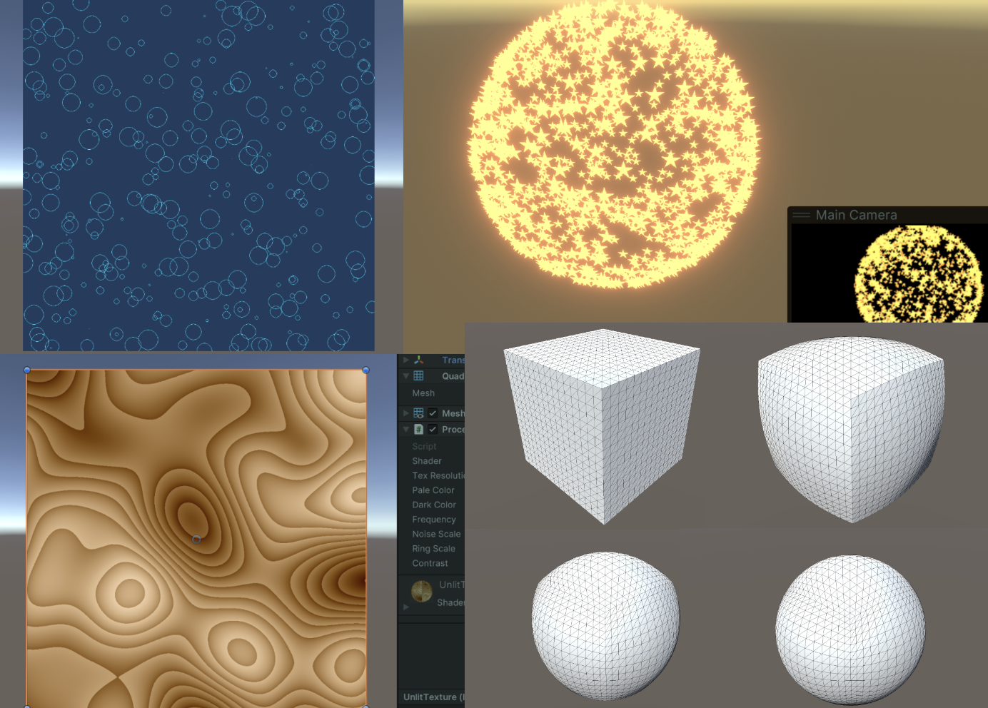
4. 使用噪声
使用Compute Shader生成一张噪声图非常简单,并且非常高效。
float random (float2 pt, float seed) {
    const float a = 12.9898;
    const float b = 78.233;
    const float c = 43758.543123;
    return frac(sin(seed + dot(pt, float2(a, b))) * c );
}

[numthreads(8,8,1)]
void CSMain (uint3 id : SV_DispatchThreadID)
{
    float4 white = 1;
    Result[id.xy] = random(((float2)id.xy)/(float)texResolution, time) * white;
}
有一个库可以得到更多各式各样的噪声。https://pastebin.com/uGhMLKeM
#include "noiseSimplex.cginc" // Paste the code above and named "noiseSimplex.cginc"

...

[numthreads(8,8,1)]
void CSMain (uint3 id : SV_DispatchThreadID)
{
    float3 pos = (((float3)id)/(float)texResolution) * 2.0;
    float n = snoise(pos);
    float ring = frac(noiseScale * n);
    float delta = pow(ring, ringScale) + n;

    Result[id.xy] = lerp(darkColor, paleColor, delta);
}
5. 变形的Mesh
这一节中,我们将一个Cube正方体,通过Compute Shader变成一个球体,并且要有动画过程,是渐变的!

老样子,在CPU端声明顶点参数,然后丢到GPU里面计算,计算得到的新坐标newPos,应用到Mesh上。
顶点结构的声明,CPU端的声明我们附带一个构造函数,这样方便些。GPU端的照葫芦画瓢。此处,我们打算向GPU传递两个Buffer,一个只读另一个可读写。一开始两个Buffer是一样的,随着时间变化(渐变),可读写的Buffer逐渐变化,Mesh从立方体不断变成球球。
// CPU
public struct Vertex
{
    public Vector3 position;
    public Vector3 normal;
    public Vertex( Vector3 p, Vector3 n )
    {
        position.x = p.x;
        position.y = p.y;
        position.z = p.z;
        normal.x = n.x;
        normal.y = n.y;
        normal.z = n.z;
    }
}
...
Vertex[] vertexArray;
Vertex[] initialArray;
ComputeBuffer vertexBuffer;
ComputeBuffer initialBuffer;
// GPU
struct Vertex {
    float3 position;
    float3 normal;
};
...
RWStructuredBuffer<Vertex>  vertexBuffer;
StructuredBuffer<Vertex>    initialBuffer;
初始化( Start() 函数)的完整步骤如下:
- 在CPU端,初始化kernel,获取Mesh引用
- 将Mesh数据传到CPU中
- 在GPU中声明Mesh数据的Buffer
- 将Mesh数据和其他参数传到GPU中
完成这些操作后,每一帧Update,我们将从GPU得到的新顶点,应用给mesh。
那GPU的计算怎么实现呢?
相当简单的做法,我们只需要归一化模型空间的各个顶点即可!试想一下,当所有顶点位置向量都归一化了,那模型就变成一个球。

实际代码中,我们还需要同时计算法线,如果不改变法线,物体的光照就会非常奇怪。那问题来了,法线怎么计算呢?非常简单,原本正方体的顶点的坐标就是最终球球的法线向量!

为了实现“呼吸”的效果,加入一个正弦函数,控制归一化的系数。
float delta = (Mathf.Sin(Time.time) + 1)/ 2;由于代码有点长,放一个链接吧。
当前版本代码:
- Compute Shader:https://github.com/Remyuu/Unity-Compute-Shader-Learn/blob/L2_Mesh_Cube2Sphere/Assets/Shaders/MeshDeform.compute
- CPU:https://github.com/Remyuu/Unity-Compute-Shader-Learn/blob/L2_Mesh_Cube2Sphere/Assets/Scripts/MeshDeform.cs

6. 总结/小测试
应该如何在GPU上定义这个结构:
struct Circle
{
    public Vector2 origin;
    public Vector2 velocity;
    public float radius;
}
这个结构应该怎样设置ComputeBuffer的大小?
struct Circle
{
    public Vector2 origin;
    public Vector2 velocity;
    public float radius;
}
下面代码为什么错误?
StructuredBuffer<float3> positions;
//Inside a kernel
...
positions[id.x] = fixed3(1,0,0);
发表回复