
前言
初步认识了Compute Shader,实现一些简单的效果。所有的代码都在:
https://github.com/Remyuu/Unity-Compute-Shader-Learngithub.com/Remyuu/Unity-Compute-Shader-Learn
main分支是初始代码,可以下载完整的工程跟着我敲一遍。PS:每一个版本的代码我都单独开了分支。

这一篇文章学习如何使用Compute Shader制作:
- 后处理效果
- 粒子系统
上一篇文章没有提及GPU的架构,是因为我觉得一上来就解释一大堆名词根本听不懂QAQ。有了实际编写Compute Shader的经验,就可以将抽象的概念和实际的代码联系起来。
CUDA在GPU上的执行程序可以用三层架构来说明:
- Grid – 对应一个Kernel
- |-Block – 一个Grid有多个Block,执行相同的程序
- | |-Thread – GPU上最基本的运算单元

Thread是GPU最基础的单元,不同Thread中自然就会有信息交换。为了有效地支持大量并行线程的运行,并解决这些线程之间的数据交换需求,内存被设计成多个层次。因此存储角度也可以分为三层:
- Per-Thread memory – 一个Thread内,传输周期是一个时钟周期(小于1纳秒),速度可以比全局内存快几百倍。
- Shared memory – 一个Block之间,速度比全局快很多。
- Global memory – 所有线程之间,但速度最慢,通常是GPU的瓶颈。Volta架构使用了HBM2作为设备的全局内存,Turing则是用了GDDR6。
如果超过内存大小限制,则会被推到容量更大但是更慢的存储空间上。
Shared Memory和L1 cache共享同一个物理空间,但是功能上有区别:前者需要手动管理,后者由硬件自动管理。我的理解是,Shared Memory 功能上类似于一个可编程的L1缓存。

在NVIDIA的CUDA架构中,流式多处理器(Streaming Multiprocessor, SM)是GPU上的一个处理单元,负责执行分配给它的线程块(Blocks)中的线程。流处理器(Stream Processors),也称为“CUDA核心”,是SM内的处理元件,每个流处理器可以并行处理多个线程。总的来说:
- GPU -> Multi-Processors (SMs) -> Stream Processors
即,GPU包含多个SM(也就是多处理器),每个SM包含多个流处理器。每个流处理器负责执行一个或多个线程(Thread)的计算指令。
在GPU中,Thread(线程)是执行计算的最小单元,Warp(纬度)是CUDA中的基本执行单位。
在NVIDIA的CUDA架构中,每个Warp通常包含32个线程(AMD有64个)。Block(块)是一个线程组,包含多个线程。在CUDA中,一个Block可以包含多个Warp。Kernel(内核)是在GPU上执行的一个函数,你可以将其视为一段特定的代码,这段代码被所有激活的线程并行执行。总的来说:
- Kernel -> Grid -> Blocks -> Warps -> Threads
但在日常开发中,通常需要同时执行的线程(Threads)远超过32个。
为了解决软件需求与硬件架构之间的数量不匹配问题,GPU采用了一种策略:将属于同一个块(Block)的线程分组。这种分组被称为“Warp”,每个Warp包含固定数量的线程。当需要执行的线程数量超过一个Warp所能包含的数量时,GPU会调度额外的Warp。这样做的原则是确保没有任何线程被遗漏,即便这意味着需要启动更多的Warp。
举个例子,如果一个块(Block)有128个线程(Thread),并且我的显卡身穿皮夹克(Nvidia每个Warp有32个Thread),那么一个块(Block)就会有 128/32=4 个Warp。举一个极端的例子,如果有129个线程,那么就会开5个Warp。有31个线程位置将直接空闲!因此我们在写Compute Shader时,[numthreads(a,b,c)] 中的 abc 最好是32的倍数,减少CUDA核心的浪费。
读到这里,想必你一定会很混乱。我按照个人的理解画了个图。若有错误请指出。

L3 后处理效果
当前构建基于BIRP管线,SRP管线只需要修改几处代码。
这一章关键在于构建一个抽象基类管理Compute Shader所需的资源(第一节)。然后基于这个抽象基类,编写一些简单的后处理效果,比如高斯模糊、灰阶效果、低分辨率像素效果以及夜视仪效果等等。这一章的知识点的小总结:
- 获取和处理Camera的渲染贴图
- ExecuteInEditMode 关键词
- SystemInfo.supportsComputeShaders 检查系统是否支持
- Graphics.Blit() 函数的使用(全程是Bit Block Transfer)
- 用 smoothstep() 制作各种效果
- 多个Kernel之间传输数据 Shared 关键词
1. 介绍与准备工作
后处理效果需要准备两张贴图,一个只读,另一个可读写。至于贴图从哪来,都说是后处理了,那肯定从相机身上获取贴图,也就是Camera组件上的Target Texture。
- Source:只读
- Destination:可读写,用于最终输出

由于后续会实现多种后处理效果,因此抽象出一个基类,减少后期工作量。
在基类中封装以下特性:
- 初始化资源(创建贴图、Buffer等)
- 管理资源(比方说屏幕分辨率改变后,重新创建Buffer等等)
- 硬件检查(检查当前设备是否支持Compute Shader)
抽象类完整代码链接:https://pastebin.com/9pYvHHsh
首先,当脚本实例被激活或者附加到活着的GO的时候,调用 OnEnable() 。在里面写初始化的操作。检查硬件是否支持、检查Compute Shader是否在Inspector上绑定、获取指定的Kernel、获取当前GO的Camera组件、创建纹理以及设置初始化状态为真。
if (!SystemInfo.supportsComputeShaders)
    ...
if (!shader)
    ...
kernelHandle = shader.FindKernel(kernelName);
thisCamera = GetComponent<Camera>();
if (!thisCamera)
    ...
CreateTextures();
init = true;
创建两个纹理 CreateTextures() ,一个Source一个Destination,尺寸为摄像机分辨率。
texSize.x = thisCamera.pixelWidth;
texSize.y = thisCamera.pixelHeight;
if (shader)
{
    uint x, y;
    shader.GetKernelThreadGroupSizes(kernelHandle, out x, out y, out _);
    groupSize.x = Mathf.CeilToInt((float)texSize.x / (float)x);
    groupSize.y = Mathf.CeilToInt((float)texSize.y / (float)y);
}
CreateTexture(ref output);
CreateTexture(ref renderedSource);
shader.SetTexture(kernelHandle, "source", renderedSource);
shader.SetTexture(kernelHandle, "outputrt", output);
具体纹理的创建:
protected void CreateTexture(ref RenderTexture textureToMake, int divide=1)
{
    textureToMake = new RenderTexture(texSize.x/divide, texSize.y/divide, 0);
    textureToMake.enableRandomWrite = true;
    textureToMake.Create();
}
这样就完成初始化了,当摄像机完成场景渲染并准备显示到屏幕上时,Unity会调用 OnRenderImage() ,这个时候就开始调用Compute Shader开始计算了。若当前没初始化好或者没shader,就Blit一下,把source直接拷给destination,即啥也不干。 CheckResolution(out _) 这个方法检查渲染纹理的分辨率是否需要更新,如果要,就重新生成一下Texture。完事之后,就到了老生常谈的Dispatch阶段啦。这里就需要将source贴图通过Buffer传给GPU,计算完毕后,传回给destination。
protected virtual void OnRenderImage(RenderTexture source, RenderTexture destination)
{
    if (!init || shader == null)
    {
        Graphics.Blit(source, destination);
    }
    else
    {
        CheckResolution(out _);
        DispatchWithSource(ref source, ref destination);
    }
}
注意看,这里我们没有用什么 SetData() 或者是 GetData() 之类的操作。因为现在所有数据都在GPU上,我们直接命令GPU自产自销就好了,CPU不要趟这滩浑水。如果将纹理取回内存,再传给GPU,性能就相当糟糕。
protected virtual void DispatchWithSource(ref RenderTexture source, ref RenderTexture destination)
{
    Graphics.Blit(source, renderedSource);
    shader.Dispatch(kernelHandle, groupSize.x, groupSize.y, 1);
    Graphics.Blit(output, destination);
}
我不信邪,非得传回CPU再传回GPU,测试结果相当震惊,性能竟然差了4倍以上。因此我们需要减少CPU和GPU之间的通信,这是使用Compute Shader时非常需要关心的。
// 笨蛋方法
protected virtual void DispatchWithSource(ref RenderTexture source, ref RenderTexture destination)
{
    // 将源贴图Blit到用于处理的贴图
    Graphics.Blit(source, renderedSource);
    // 使用计算着色器处理贴图
    shader.Dispatch(kernelHandle, groupSize.x, groupSize.y, 1);
    // 将输出贴图复制到一个Texture2D对象中,以便读取数据到CPU
    Texture2D tempTexture = new Texture2D(renderedSource.width, renderedSource.height, TextureFormat.RGBA32, false);
    RenderTexture.active = output;
    tempTexture.ReadPixels(new Rect(0, 0, output.width, output.height), 0, 0);
    tempTexture.Apply();
    RenderTexture.active = null;
    // 将Texture2D数据传回GPU到一个新的RenderTexture
    RenderTexture tempRenderTexture = RenderTexture.GetTemporary(output.width, output.height);
    Graphics.Blit(tempTexture, tempRenderTexture);
    // 最终将处理后的贴图Blit到目标贴图
    Graphics.Blit(tempRenderTexture, destination);
    // 清理资源
    RenderTexture.ReleaseTemporary(tempRenderTexture);
    Destroy(tempTexture);
}
接下来开始编写第一个后处理效果。
小插曲:奇怪的BUG
另外插播一个奇怪bug。
在Compute Shader中,如果最终输出的贴图结果名字是output,那么在某些API比如Metal中,就会出问题。解决方法是,改个名字。
RWTexture2D<float4> outputrt;
添加图片注释,不超过 140 字(可选)
2. RingHighlight效果

创建RingHighlight类,继承自刚刚编写的基类。

重载初始化方法,指定Kernel。
protected override void Init()
{
    center = new Vector4();
    kernelName = "Highlight";
    base.Init();
}
重载渲染方法。想要实现聚焦某个角色的效果,则需要给Compute Shader传入角色的屏幕空间的坐标 center 。并且,如果在Dispatch之前,屏幕分辨率发生改变,那么重新初始化。
protected void SetProperties()
{
    float rad = (radius / 100.0f) * texSize.y;
    shader.SetFloat("radius", rad);
    shader.SetFloat("edgeWidth", rad * softenEdge / 100.0f);
    shader.SetFloat("shade", shade);
}
protected override void OnRenderImage(RenderTexture source, RenderTexture destination)
{
    if (!init || shader == null)
    {
        Graphics.Blit(source, destination);
    }
    else
    {
        if (trackedObject && thisCamera)
        {
            Vector3 pos = thisCamera.WorldToScreenPoint(trackedObject.position);
            center.x = pos.x;
            center.y = pos.y;
            shader.SetVector("center", center);
        }
        bool resChange = false;
        CheckResolution(out resChange);
        if (resChange) SetProperties();
        DispatchWithSource(ref source, ref destination);
    }
}
并且改变Inspector面板的时候可以实时看到参数变化效果,添加 OnValidate() 方法。
private void OnValidate()
{
    if(!init)
        Init();
    SetProperties();
}
GPU中,该怎么制作一个圆内没有阴影,圆的边缘平滑过渡,过渡层外是阴影的效果呢?基于上一篇文章判断一个点是否在圆内的方法,我们用 smoothstep() ,处理过渡层即可。
#pragma kernel Highlight

Texture2D<float4> source;
RWTexture2D<float4> outputrt;
float radius;
float edgeWidth;
float shade;
float4 center;

float inCircle( float2 pt, float2 center, float radius, float edgeWidth ){
    float len = length(pt - center);
    return 1.0 - smoothstep(radius-edgeWidth, radius, len);
}

[numthreads(8, 8, 1)]
void Highlight(uint3 id : SV_DispatchThreadID)
{
    float4 srcColor = source[id.xy];
    float4 shadedSrcColor = srcColor * shade;
    float highlight = inCircle( (float2)id.xy, center.xy, radius, edgeWidth);
    float4 color = lerp( shadedSrcColor, srcColor, highlight );

    outputrt[id.xy] = color;

}
当前版本代码:
- Compute Shader:https://github.com/Remyuu/Unity-Compute-Shader-Learn/blob/L3_RingHighlight/Assets/Shaders/RingHighlight.compute
- CPU:https://github.com/Remyuu/Unity-Compute-Shader-Learn/blob/L3_RingHighlight/Assets/Scripts/RingHighlight.cs
3. 模糊效果

模糊效果原理很简单,每一个像素采样周边的 n*n 个像素加权平均就可以得到最终效果。
但是有效率问题。众所周知,减少对纹理的采样次数对优化非常重要。如果每个像素都需要采样20*20个周边像素,那么渲染一个像素就需要采样400次,显然是无法接受的。并且,对于单个像素而言,采集周边一整个矩形像素的操作在Compute Shader中很难处理。怎么解决呢?
通常做法是,横着采样一遍,再竖着采样一遍。什么意思呢?对于每一个像素,只在x方向上采样20个像素,y方向上采样20个像素,总共采样20+20个像素,再加权平均。这种方法不仅减少了采样次数,还更符合Compute Shader的逻辑。横着采样,设置一个Kernel;竖着采样,设置另一个Kernel。
#pragma kernel HorzPass
#pragma kernel Highlight
由于Dispatch是顺序执行的,因此我们计算完水平的模糊后,利用计算好的结果再垂直采样一遍。
shader.Dispatch(kernelHorzPassID, groupSize.x, groupSize.y, 1);
shader.Dispatch(kernelHandle, groupSize.x, groupSize.y, 1);
做完模糊操作之后,再结合上一节的RingHighlight,完工!
有一点不同的是,再计算完水平模糊后,怎么将结果传给下一个Kernel呢?答案呼之欲出了,直接使用 shared 关键词。具体步骤如下。
CPU中声明存储水平模糊纹理的引用,制作水平纹理的kernel,并绑定。
RenderTexture horzOutput = null;
int kernelHorzPassID;
protected override void Init()
{
    ...
    kernelHorzPassID = shader.FindKernel("HorzPass");
    ...
}
还需要额外在GPU中开辟空间,用来存储第一个kernel的结果。
protected override void CreateTextures()
{
    base.CreateTextures();
    shader.SetTexture(kernelHorzPassID, "source", renderedSource);
    CreateTexture(ref horzOutput);
    shader.SetTexture(kernelHorzPassID, "horzOutput", horzOutput);
    shader.SetTexture(kernelHandle, "horzOutput", horzOutput);
}
GPU上这样设置:
shared Texture2D<float4> source;
shared RWTexture2D<float4> horzOutput;
RWTexture2D<float4> outputrt;
另外有个疑问, shared 这个关键词好像加不加都一样,实际测试不同的kernel都可以访问到。那请问shared还有什么意义呢?
在Unity中,变量前加shared表示这个资源不是每次调用都重新初始化,而是保持其状态,供不同的shader或dispatch调用使用。这有助于在不同的shader调用之间共享数据。标记了 shared 可以帮助编译器优化出更高性能的代码。

在计算边界的像素时,会遇到可用像素数量不足的情况。要么就是左边剩下的像素不足 blurRadius ,要么右边剩余像素不足。因此先算出安全的左索引,然后再计算从左到右最大可以取多少。
[numthreads(8, 8, 1)]
void HorzPass(uint3 id : SV_DispatchThreadID)
{
    int left = max(0, (int)id.x-blurRadius);
    int count = min(blurRadius, (int)id.x) + min(blurRadius, source.Length.x - (int)id.x);
    float4 color = 0;
    uint2 index = uint2((uint)left, id.y);
    [unroll(100)]
    for(int x=0; x<count; x++){
        color += source[index];
        index.x++;
    }
    color /= (float)count;
    horzOutput[id.xy] = color;
}
[numthreads(8, 8, 1)]
void Highlight(uint3 id : SV_DispatchThreadID)
{
    //Vert blur
    int top = max(0, (int)id.y-blurRadius);
    int count = min(blurRadius, (int)id.y) + min(blurRadius, source.Length.y - (int)id.y);
    float4 blurColor = 0;
    uint2 index = uint2(id.x, (uint)top);
    [unroll(100)]
    for(int y=0; y<count; y++){
        blurColor += horzOutput[index];
        index.y++;
    }
    blurColor /= (float)count;
    float4 srcColor = source[id.xy];
    float4 shadedBlurColor = blurColor * shade;
    float highlight = inCircle( (float2)id.xy, center.xy, radius, edgeWidth);
    float4 color = lerp( shadedBlurColor, srcColor, highlight );
    outputrt[id.xy] = color;
}
当前版本代码:
- Compute Shader:https://github.com/Remyuu/Unity-Compute-Shader-Learn/blob/L3_BlurEffect/Assets/Shaders/BlurHighlight.compute
- CPU:https://github.com/Remyuu/Unity-Compute-Shader-Learn/blob/L3_BlurEffect/Assets/Scripts/BlurHighlight.cs
4. 高斯模糊
和上面不同的是,采样之后不再是取平均值,而是用一个高斯函数加权求得。
其中, 是标准差,控制宽度。
有关更多Blur的内容:https://www.gamedeveloper.com/programming/four-tricks-for-fast-blurring-in-software-and-hardware#close-modal
由于这个计算量还有不小的,如果每一个像素都去计算一次这个式子就非常耗。我们用预计算的方式,将计算结果通过Buffer的方式传到GPU上。由于两个kernel都需要使用,在Buffer声明的时候加一个shared。
float[] SetWeightsArray(int radius, float sigma)
{
    int total = radius * 2 + 1;
    float[] weights = new float[total];
    float sum = 0.0f;
    for (int n=0; n<radius; n++)
    {
        float weight = 0.39894f * Mathf.Exp(-0.5f * n * n / (sigma * sigma)) / sigma;
        weights[radius + n] = weight;
        weights[radius - n] = weight;
        if (n != 0)
            sum += weight * 2.0f;
        else
            sum += weight;
    }
    // normalize kernels
    for (int i=0; i<total; i++) weights[i] /= sum;
    return weights;
}
private void UpdateWeightsBuffer()
{
    if (weightsBuffer != null)
        weightsBuffer.Dispose();
    float sigma = (float)blurRadius / 1.5f;
    weightsBuffer = new ComputeBuffer(blurRadius * 2 + 1, sizeof(float));
    float[] blurWeights = SetWeightsArray(blurRadius, sigma);
    weightsBuffer.SetData(blurWeights);
    shader.SetBuffer(kernelHorzPassID, "weights", weightsBuffer);
    shader.SetBuffer(kernelHandle, "weights", weightsBuffer);
}
完整代码:
- https://pastebin.com/0qWtUKgy
- https://pastebin.com/A6mDKyJE
5. 低分辨率效果
GPU:真是酣畅淋漓的计算啊。

让一张高清的纹理边模糊,同时不修改分辨率。实现方法很简单,每 n*n 个像素,都只取左下角的像素颜色即可。利用整数的特性,id.x索引先除n,再乘上n就可以了。
uint2 index = (uint2(id.x, id.y)/3) * 3;
float3 srcColor = source[index].rgb;
float3 finalColor = srcColor;
效果已经放在上面了。但是这个效果太锐利了,通过添加噪声,柔化锯齿。
uint2 index = (uint2(id.x, id.y)/3) * 3;
float noise = random(id.xy, time);
float3 srcColor = lerp(source[id.xy].rgb, source[index],noise);
float3 finalColor = srcColor;
每 n*n 个格子的像素不在只取左下角的颜色,而是取原本颜色和左下角颜色的随机插值结果。效果一下子就精细了不少。当n比较大的时候,还能看到下面这样的效果。只能说不太好看,但是在一些故障风格道路中还是可以继续探索。

如果想要得到噪声感的画面,可以尝试lerp的两端添加系数,比如:
float3 srcColor = lerp(source[id.xy].rgb * 2, source[index],noise);
6. 灰阶效果与染色
Grayscale Effect & Tinted
将彩色图像转换为灰阶图像的过程涉及将每个像素的RGB值转换为一个单一的颜色值。这个颜色值是RGB值的加权平均值。这里有两种方法,一种是简单平均,一种是符合人眼感知的加权平均。
- 平均值法(简单但不准确):
这种方法对所有颜色通道给予相同的权重。 2. 加权平均法(更准确, 反映人眼感知):
这种方法根据人眼对绿色更敏感、对红色次之、对蓝色最不敏感的特点, 给予不同颜色通道不同的权重。(下面的截图效果不太好,我也没看出来lol)

加权后,再简单地颜色混合(乘法),最后lerp得到可控的染色强度结果。
uint2 index = (uint2(id.x, id.y)/6) * 6;
float noise = random(id.xy, time);
float3 srcColor = lerp(source[id.xy].rgb, source[index],noise);
// float3 finalColor = srcColor;
float3 grayScale = (srcColor.r+srcColor.g+srcColor.b)/3.0;
// float3 grayScale = srcColor.r*0.299f+srcColor.g*0.587f+srcColor.b*0.114f;
float3 tinted = grayScale * tintColor.rgb;
float3 finalColor = lerp(srcColor, tinted, tintStrength);
outputrt[id.xy] = float4(finalColor, 1);
染一个废土颜色:

7. 屏幕扫描线效果
首先 uvY 将坐标归一化到 [0,1] 。
lines 是控制扫描线数量的一个参数。
然后增加一个时间偏移,系数控制偏移速度。可以开放一个参数控制线条偏移的速度。
float uvY = (float)id.y/(float)source.Length.y;
float scanline = saturate(frac(uvY * lines + time * 3));
这个“线”看起来不太够“线”,减个肥。
float uvY = (float)id.y/(float)source.Length.y;
float scanline = saturate(smoothstep(0.1,0.2,frac(uvY * lines + time * 3)));
然后lerp上颜色。
float uvY = (float)id.y/(float)source.Length.y;
float scanline = saturate(smoothstep(0.1, 0.2, frac(uvY * lines + time*3)) + 0.3);
finalColor = lerp(source[id.xy].rgb*0.5, finalColor, scanline);
“减肥”前后,各取所需吧!

8. 夜视仪效果
这一节总结上面所有内容,实现一个夜视仪的效果。先做一个单眼效果。
float2 pt = (float2)id.xy;
float2 center = (float2)(source.Length >> 1);
float inVision = inCircle(pt, center, radius, edgeWidth);
float3 blackColor = float3(0,0,0);
finalColor = lerp(blackColor, finalColor, inVision);
双眼效果不同点在于有两个圆心,计算得到的两个遮罩vision用 max() 或者是 saturate() 合并即可。
float2 pt = (float2)id.xy;
float2 centerLeft = float2(source.Length.x / 3.0, source.Length.y /2);
float2 centerRight = float2(source.Length.x / 3.0 * 2.0, source.Length.y /2);
float inVisionLeft = inCircle(pt, centerLeft, radius, edgeWidth);
float inVisionRight = inCircle(pt, centerRight, radius, edgeWidth);
float3 blackColor = float3(0,0,0);
// float inVision = max(inVisionLeft, inVisionRight);
float inVision = saturate(inVisionLeft + inVisionRight);
finalColor = lerp(blackColor, finalColor, inVision);
当前版本代码:
- Compute Shader:https://github.com/Remyuu/Unity-Compute-Shader-Learn/blob/L3_NightVision/Assets/Shaders/NightVision.compute
- CPU:https://github.com/Remyuu/Unity-Compute-Shader-Learn/blob/L3_NightVision/Assets/Scripts/NightVision.cs
9. 平缓过渡线条
思考一下,我们应该怎么在屏幕上画一条平滑过渡的直线。

smoothstep() 函数可以完成这个操作,熟悉这个函数的读者可以略过这一段。这个函数用来创建平滑的渐变。smoothstep(edge0, edge1, x) 函数在x在 edge0 和 edge1 之间时,输出值从0渐变到1。如果 x < edge0 ,返回0;如果 x > edge1 ,返回1。其输出值是根据Hermite插值计算的:

float onLine(float position, float center, float lineWidth, float edgeWidth) {
    float halfWidth = lineWidth / 2.0;
    float edge0 = center - halfWidth - edgeWidth;
    float edge1 = center - halfWidth;
    float edge2 = center + halfWidth;
    float edge3 = center + halfWidth + edgeWidth;
    return smoothstep(edge0, edge1, position) - smoothstep(edge2, edge3, position);
}
上面代码中,传入的参数都已经归一化 [0,1]。position 是考察的点的位置,center 是线的中心位置,lineWidth 是线的实际宽度,edgeWidth 是边缘的宽度,用于平滑过渡。我实在对我的表达能力感到不悦!至于怎么算的,我给大家画个图理解吧!
大概就是:, ,。

思考一下,怎么画一个平滑过渡的圆。
对于每个点,先计算与圆心的距离向量,结果返回给 position ,并且计算其长度返回给 len 。
模仿上面两个 smoothstep 做差的方法,通过减去外边缘插值结果来生成一个环形的线条效果。
float circle(float2 position, float2 center, float radius, float lineWidth, float edgeWidth){
    position -= center;
    float len = length(position);
    //Change true to false to soften the edge
    float result = smoothstep(radius - lineWidth / 2.0 - edgeWidth, radius - lineWidth / 2.0, len) - smoothstep(radius + lineWidth / 2.0, radius + lineWidth / 2.0 + edgeWidth, len);
    return result;
}
10. 扫描线效果
然后一条横线、一条竖线,套娃几个圆,做一个雷达扫描的效果。
float3 color = float3(0.0f,0.0f,0.0f);
color += onLine(uv.y, center.y, 0.002, 0.001) * axisColor.rgb;//xAxis
color += onLine(uv.x, center.x, 0.002, 0.001) * axisColor.rgb;//yAxis
color += circle(uv, center, 0.2f, 0.002, 0.001) * axisColor.rgb;
color += circle(uv, center, 0.3f, 0.002, 0.001) * axisColor.rgb;
color += circle(uv, center, 0.4f, 0.002, 0.001) * axisColor.rgb;
再画一个扫描线,并且带有轨迹。
float sweep(float2 position, float2 center, float radius, float lineWidth, float edgeWidth) {
    float2 direction = position - center;
    float theta = time + 6.3;
    float2 circlePoint = float2(cos(theta), -sin(theta)) * radius;
    float projection = clamp(dot(direction, circlePoint) / dot(circlePoint, circlePoint), 0.0, 1.0);
    float lineDistance = length(direction - circlePoint * projection);
    float gradient = 0.0;
    const float maxGradientAngle = PI * 0.5;
    if (length(direction) < radius) {
        float angle = fmod(theta + atan2(direction.y, direction.x), PI2);
        gradient = clamp(maxGradientAngle - angle, 0.0, maxGradientAngle) / maxGradientAngle * 0.5;
    }
    return gradient + 1.0 - smoothstep(lineWidth, lineWidth + edgeWidth, lineDistance);
}
添加到颜色中。
...
color += sweep(uv, center, 0.45f, 0.003, 0.001) * sweepColor.rgb;
...
当前版本代码:
- Compute Shader:https://github.com/Remyuu/Unity-Compute-Shader-Learn/blob/L3_HUDOverlay/Assets/Shaders/HUDOverlay.compute
- CPU:https://github.com/Remyuu/Unity-Compute-Shader-Learn/blob/L3_HUDOverlay/Assets/Scripts/HUDOverlay.cs
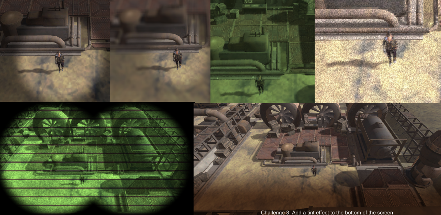
11. 渐变背景阴影效果
这个效果可以用在字幕或者是一些说明性文字之下。虽然可以直接在UI Canvas中加一张贴图,但是使用Compute Shader可以实现更加灵活的效果以及资源的优化。

字幕、对话文字背景一般都在屏幕下方,上方不作处理。同时需要较高的对比度,因此对原有画面做一个灰度处理、并且指定一个阴影。
if (id.y<(uint)tintHeight){
    float3 grayScale = (srcColor.r + srcColor.g + srcColor.b) * 0.33 * tintColor.rgb;
    float3 shaded = lerp(srcColor.rgb, grayScale, tintStrength) * shade;
    ... // 接下文
}else{
    color = srcColor;
}
渐变效果。
...// 接上文
    float srcAmount = smoothstep(tintHeight-edgeWidth, (float)tintHeight, (float)id.y);
    ...// 接下文
最后再lerp起来。
...// 接上文
    color = lerp(float4(shaded, 1), srcColor, srcAmount);
12. 总结/小测试
If id.xy = [ 100, 30 ]. What would be the return value of inCircle((float2)id.xy, float2(130, 40), 40, 0.1)

When creating a blur effect which answer describes our approach best?

Which answer would create a blocky low resolution version of the source image?

What is smoothstep(5, 10, 6); ?

If an and b are both vectors. Which answer best describes dot(a,b)/dot(b,b); ?

What is _MainTex_TexelSize.x? If _MainTex is 512 x 256 pixel resolution.

13. 利用Blit结合Material做后处理
除了使用Compute Shader制作后处理,还有一种简单的方法。
// .cs
Graphics.Blit(source, dest, material, passIndex);
// .shader
Pass{
    CGPROGRAM
    #pragma vertex vert_img
    #pragma fragment frag
    fixed4 frag(v2f_img input) : SV_Target{
        return tex2D(_MainTex, input.uv);
    }
    ENDCG
}
通过结合Shader来处理图像数据。
那么问题来了,两者有什么区别?而且传进来的不是一张纹理吗,哪来的顶点?
答:
第一个问题。这种方法称为“屏幕空间着色”,完全集成在Unity的图形管线中,性能其实比Compute Shader更高。而Compute Shader提供了对GPU资源的更细粒度控制。它不受图形管线的限制,可以直接访问和修改纹理、缓冲区等资源。
第二个问题。注意看 vert_img 。在UnityCG中可以找到如下定义:


Unity会自动将传进来的纹理自动转换为两个三角形(一个充满屏幕的矩形),我们用材质的方法编写后处理时直接在frag上写就好了。
下一章将会学习如何将Material、Shader、Compute Shader还有C#联系起来。
发表回复