
紧接着上一篇文章
remoooo:Compute Shader学习笔记(二)之 后处理效果
L4 粒子效果与群集行为模拟
本章节使用Compute Shader生成粒子。学习如何使用DrawProcedural和DrawMeshInstancedIndirect,也就是GPU Instancing。
知识点总结:
- Compute Shader、Material、C#脚本和Shader共同协作
- Graphics.DrawProcedural
- material.SetBuffer()
- xorshift 随机算法
- 集群行为模拟
- Graphics.DrawMeshInstancedIndirect
- 旋转平移缩放矩阵,齐次坐标
- Surface Shader
- ComputeBufferType.Default
- #pragma instancing_options procedural:setup
- unity_InstanceID
- Skinned Mesh Renderer
- 数据对齐
1. 介绍与准备工作
Compute Shader除了可以同时处理大量的数据,还有一个关键的优势,就是Buffer存储在GPU中。因此可以将Compute Shader处理好的数据直接传递给与Material关联的Shader中,即Vertex/Fragment Shader。这里的关键就是,material也可以像Compute Shader一样SetBuffer(),直接从GPU的Buffer中访问数据!

使用Compute Shader来制作粒子系统可以充分体现Compute Shader的强大并行能力。
在渲染过程中,Vertex Shader会从Compute Buffer中读取每个粒子的位置和其他属性,并将它们转换为屏幕上的顶点。Fragment Shader则负责根据这些顶点的信息(如位置和颜色)来生成像素。通过Graphics.DrawProcedural方法,Unity可以直接渲染这些由Shader处理的顶点,无需预先定义的网格结构,也不依赖Mesh Renderer,这对于渲染大量粒子特别有效。
2. 粒子你好
步骤也是非常简单,在 C# 中定义好粒子的信息(位置、速度与生命周期),初始化将数据传给Buffer,绑定Buffer到Compute Shader和Material。渲染阶段在OnRenderObject()里调用Graphics.DrawProceduralNow实现高效地渲染粒子。

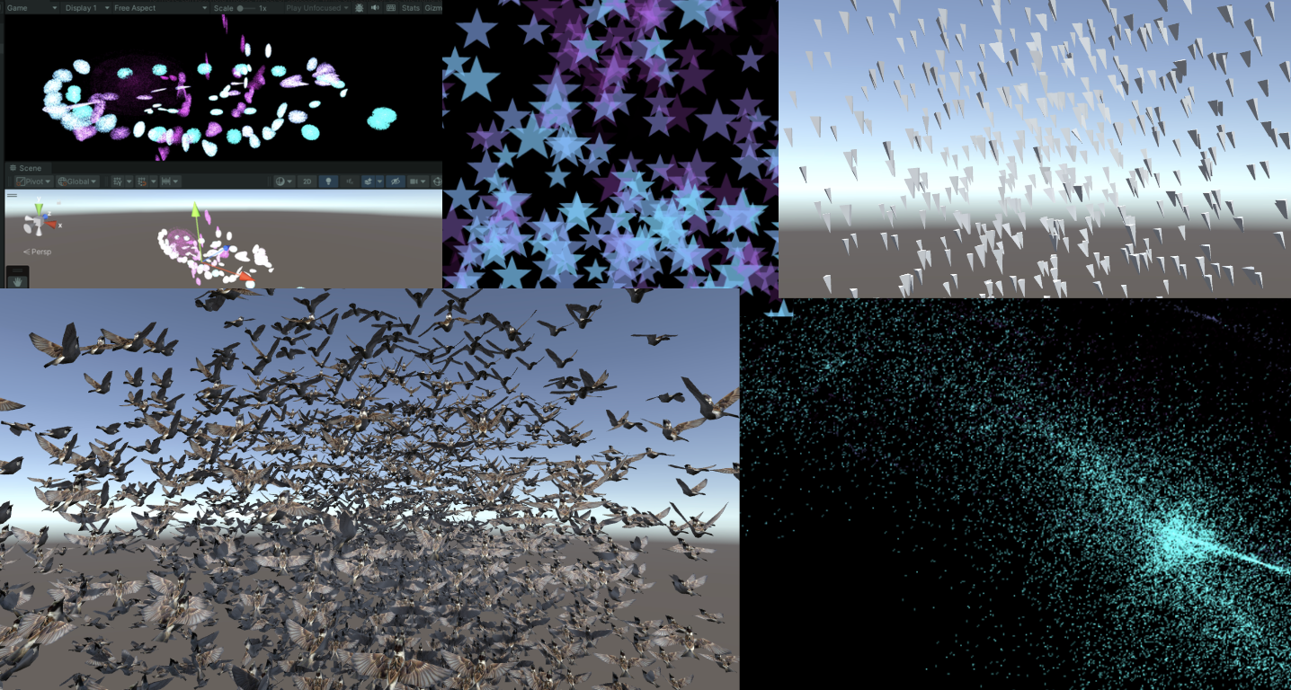
新建一个场景,制作一个效果:百万粒子跟随鼠标绽放生命的粒子,如下:

写到这里,不禁让我思绪万千。粒子的生命周期很短暂,如同星火一般瞬间点燃,又如同流星一闪即逝。纵有千百磨难,我亦不过是亿万尘埃中的一粒,平凡且渺小。这些粒子,虽或许会在空间中随机漂浮(使用”Xorshift”算法计算粒子生成的位置),或许会拥有独一无二的色彩,但它们终究逃不出被程式预设的命运。这难道不正是我的人生写照吗?按部就班地上演着自己的角色,无法逃脱那无形的束缚。
“上帝已死!而我们这些杀死他的人,又怎能不感到最大的痛苦呢?” – 弗里德里希·尼采
尼采不仅宣告了宗教信仰的消逝,更指出了现代人面临的虚无感,即没有了传统的道德和宗教支柱,人们感到了前所未有的孤独和方向感的缺失。粒子在C#脚本中被定义、创造,按照特定规则运动和消亡,这与尼采所描述的现代人在宇宙中的状态颇有相似之处。虽然每个人都试图寻找自己的意义,但最终仍受限于更广泛的社会和宇宙规则。
生活中充满了各种不可避免的痛苦,反映了人类存在的固有虚无和孤独感。失恋、生离死别、工作失意以及即将编写的粒子死亡逻辑等等,都印证了尼采所表达的,生活中没有什么是永恒不变的。同一个Buffer中的粒子必然在未来某个时刻消失,这体现了尼采所描述的现代人的孤独感,个体可能会感受到前所未有的孤立无援,因此每个人都是孤独的战士,必须学会独自面对内心的龙卷风和外部世界的冷漠。
但是没关系,「夏天会周而复始,该相逢的人会再次相逢」。本文的粒子也会在结束后再次生成,以最好的状态拥抱属于它的Buffer。
Summer will come around again. People who meet will meet again.

当前版本代码,可以自己拷下来跑跑(都有注释):
- Compute Shader:https://github.com/Remyuu/Unity-Compute-Shader-Learn/blob/L4_First_Particle/Assets/Shaders/ParticleFun.compute
- CPU:https://github.com/Remyuu/Unity-Compute-Shader-Learn/blob/L4_First_Particle/Assets/Scripts/ParticleFun.cs
- Shader:https://github.com/Remyuu/Unity-Compute-Shader-Learn/blob/L4_First_Particle/Assets/Shaders/Particle.shader
废话就说到这,先看看 C# 脚本是咋写的。

老样子,先定义粒子的Buffer(结构体),并且初始化一下子,然后传给GPU,关键在于最后三行将Buffer绑定给shader的操作。下面省略号的代码没什么好讲的,都是常规操作,用注释一笔带过了。
struct Particle{
    public Vector3 position; // 粒子位置
    public Vector3 velocity; // 粒子速度
    public float life;       // 粒子生命周期
}
ComputeBuffer particleBuffer; // GPU 的 Buffer
...
// Init() 中
    // 初始化粒子数组
    Particle[] particleArray = new Particle[particleCount];
    for (int i = 0; i < particleCount; i++){
        // 生成随机位置和归一化
        ...
        // 设置粒子的初始位置和速度
        ...
        // 设置粒子的生命周期
        particleArray[i].life = Random.value * 5.0f + 1.0f;
    }
    // 创建并设置Compute Buffer
    ...
    // 查找Compute Shader中的kernel ID
    ...
    // 绑定Compute Buffer到shader
    shader.SetBuffer(kernelID, "particleBuffer", particleBuffer);
    material.SetBuffer("particleBuffer", particleBuffer);
    material.SetInt("_PointSize", pointSize);
关键的渲染阶段来了 OnRenderObject() 。material.SetPass 用于设置渲染材质通道。DrawProceduralNow 方法在不使用传统网格的情况下绘制几何体。MeshTopology.Points 指定了渲染的拓扑类型为点,GPU会把每个顶点作为一个点来处理,不会进行顶点之间的连线或面的形成。第二个参数 1 表示从第一个顶点开始绘制。particleCount 指定了要渲染的顶点数,这里是粒子的数量,即告诉GPU总共需要渲染多少个点。
void OnRenderObject()
{
    material.SetPass(0);
    Graphics.DrawProceduralNow(MeshTopology.Points, 1, particleCount);
}
获取当前鼠标位置方法。OnGUI()这个方法每一帧可能调用多次。z值设为摄像机的近裁剪面加上一个偏移量,这里加14是为了得到一个更合适视觉深度的世界坐标(也可以自行调整)。
void OnGUI()
{
    Vector3 p = new Vector3();
    Camera c = Camera.main;
    Event e = Event.current;
    Vector2 mousePos = new Vector2();
    // Get the mouse position from Event.
    // Note that the y position from Event is inverted.
    mousePos.x = e.mousePosition.x;
    mousePos.y = c.pixelHeight - e.mousePosition.y;
    p = c.ScreenToWorldPoint(new Vector3(mousePos.x, mousePos.y, c.nearClipPlane + 14));
    cursorPos.x = p.x;
    cursorPos.y = p.y;
}
上面已经将 ComputeBuffer particleBuffer; 传到了Compute Shader和Shader中。
先看看Compute Shader的数据结构。没什么特别的。
// 定义粒子数据结构
struct Particle
{
    float3 position;  // 粒子的位置
    float3 velocity;  // 粒子的速度
    float life;       // 粒子的剩余生命时间
};
// 用于存储和更新粒子数据的结构化缓冲区,可从GPU读写
RWStructuredBuffer<Particle> particleBuffer;
// 从CPU设置的变量
float deltaTime;       // 从上一帧到当前帧的时间差
float2 mousePosition;  // 当前鼠标位置
这里简单讲讲一个特别好用的随机数序列生成方法 xorshift 算法。一会将用来随机粒子的运动方向如上图,粒子会随机朝着三维的方向运动。
- 详细参考:https://en.wikipedia.org/wiki/Xorshift
- 原论文链接:https://www.jstatsoft.org/article/view/v008i14
这个算法03年由George Marsaglia提出,优点在于运算速度极快,并且非常节约空间。即使是最简单的Xorshift实现,其伪随机数周期也是相当长的。
基本操作是位移(shift)和异或(xor)。算法的名字也由此而来。它的核心是维护一个非零的状态变量,通过对这个状态变量进行一系列的位移和异或操作来生成随机数。
// 用于生成随机数的状态变量
uint rng_state;
uint rand_xorshift() {
    // Xorshift algorithm from George Marsaglia's paper
    rng_state ^= (rng_state << 13);  // 将状态变量左移13位,然后与原状态进行异或
    rng_state ^= (rng_state >> 17);  // 将更新后的状态变量右移17位,再次进行异或
    rng_state ^= (rng_state << 5);   // 最后,将状态变量左移5位,进行最后一次异或
    return rng_state;                // 返回更新后的状态变量作为生成的随机数
}
基本Xorshift 算法的核心已在前面的解释中提到,不过不同的位移组合可以创建多种变体。原论文还提到了Xorshift128变体。使用128位的状态变量,通过四次不同的位移和异或操作更新状态。代码如下:

// c language Ver
uint32_t xorshift128(void) {
    static uint32_t x = 123456789;
    static uint32_t y = 362436069;
    static uint32_t z = 521288629;
    static uint32_t w = 88675123;
    uint32_t t = x ^ (x << 11);
    x = y; y = z; z = w;
    w = w ^ (w >> 19) ^ (t ^ (t >> 8));
    return w;
}
可以产生更长的周期和更好的统计性能。这个变体的周期接近 ,非常厉害。
总的来说,这个算法用在游戏开发完全足够了,只是不适合用在密码学等领域。
在Compute Shader中使用这个算法时,需要注意Xorshift算法生成的随机数范围时uint32的的范围,需要再做一个映射( [0, 2^32-1] 映射到 [0, 1]):
float tmp = (1.0 / 4294967296.0);  // 转换因子
rand_xorshift()) * tmp
而粒子运动方向是有符号的,因此只要在这个基础上减去0.5就好了。三个方向的随机运动:
float f0 = float(rand_xorshift()) * tmp - 0.5;
float f1 = float(rand_xorshift()) * tmp - 0.5;
float f2 = float(rand_xorshift()) * tmp - 0.5;
float3 normalF3 = normalize(float3(f0, f1, f2)) * 0.8f; // 缩放了运动方向
每一个Kernel需要完成的内容如下:
- 先得到Buffer中上一帧的粒子信息
- 维护粒子Buffer(计算粒子速度,更新位置、生命值),写回Buffer
- 若生命值小于0,重新生成一个粒子
生成粒子,初始位置利用刚刚Xorshift得到的随机数,定义粒子的生命值,重置速度。
// 设置粒子的新位置和生命值
particleBuffer[id].position = float3(normalF3.x + mousePosition.x, normalF3.y + mousePosition.y, normalF3.z + 3.0);
particleBuffer[id].life = 4;  // 重置生命值
particleBuffer[id].velocity = float3(0,0,0);  // 重置速度
最后是Shader的基本数据结构:
struct Particle{
    float3 position;
    float3 velocity;
    float life;
};
struct v2f{
    float4 position : SV_POSITION;
    float4 color : COLOR;
    float life : LIFE;
    float size: PSIZE;
};
// particles' data
StructuredBuffer<Particle> particleBuffer;
然后在顶点着色器计算粒子的顶点色、顶点的Clip位置以及传输一个顶点大小的信息。
v2f vert(uint vertex_id : SV_VertexID, uint instance_id : SV_InstanceID){
    v2f o = (v2f)0;
    // Color
    float life = particleBuffer[instance_id].life;
    float lerpVal = life * 0.25f;
    o.color = fixed4(1.0f - lerpVal+0.1, lerpVal+0.1, 1.0f, lerpVal);
    // Position
    o.position = UnityObjectToClipPos(float4(particleBuffer[instance_id].position, 1.0f));
    o.size = _PointSize;
    return o;
}
片元着色器计算插值颜色。
float4 frag(v2f i) : COLOR{
    return i.color;
}
至此,就可以得到上面的效果。

3. Quad粒子
上一节每一个粒子都只有一个点,没什么意思。现在把一个点变成一个Quad。在Unity中,没有Quad,只有两个三角形组成的假Quad。
开干,基于上面的代码。在 C# 中定义顶点,一个Quad的尺寸。
// struct
struct Vertex
{
    public Vector3 position;
    public Vector2 uv;
    public float life;
}
const int SIZE_VERTEX = 6 * sizeof(float);
public float quadSize = 0.1f; // Quad的尺寸
每一个粒子的的基础上,设置六个顶点的uv坐标,给顶点着色器用。并且按照Unity规定的顺序绘制。
index = i*6;
    //Triangle 1 - bottom-left, top-left, top-right
    vertexArray[index].uv.Set(0,0);
    vertexArray[index+1].uv.Set(0,1);
    vertexArray[index+2].uv.Set(1,1);
    //Triangle 2 - bottom-left, top-right, bottom-right
    vertexArray[index+3].uv.Set(0,0);
    vertexArray[index+4].uv.Set(1,1);
    vertexArray[index+5].uv.Set(1,0);
最后传递给Buffer。这里的 halfSize 目的是传给Compute Shader计算Quad的各个顶点位置用的。
vertexBuffer = new ComputeBuffer(numVertices, SIZE_VERTEX);
vertexBuffer.SetData(vertexArray);
shader.SetBuffer(kernelID, "vertexBuffer", vertexBuffer);
shader.SetFloat("halfSize", quadSize*0.5f);
material.SetBuffer("vertexBuffer", vertexBuffer);
渲染阶段把点改为三角形,有六个点。
void OnRenderObject()
{
    material.SetPass(0);
    Graphics.DrawProceduralNow(MeshTopology.Triangles, 6, numParticles);
}
在Shader中改一下设置,接收顶点数据。并且接收一张贴图用于显示。需要做alpha剔除。
_MainTex("Texture", 2D) = "white" {}
...
Tags{ "Queue"="Transparent" "RenderType"="Transparent" "IgnoreProjector"="True" }
LOD 200
Blend SrcAlpha OneMinusSrcAlpha
ZWrite Off
...
    struct Vertex{
        float3 position;
        float2 uv;
        float life;
    };
    StructuredBuffer<Vertex> vertexBuffer;
    sampler2D _MainTex;
    v2f vert(uint vertex_id : SV_VertexID, uint instance_id : SV_InstanceID)
    {
        v2f o = (v2f)0;
        int index = instance_id*6 + vertex_id;
        float lerpVal = vertexBuffer[index].life * 0.25f;
        o.color = fixed4(1.0f - lerpVal+0.1, lerpVal+0.1, 1.0f, lerpVal);
        o.position = UnityWorldToClipPos(float4(vertexBuffer[index].position, 1.0f));
        o.uv = vertexBuffer[index].uv;
        return o;
    }
    float4 frag(v2f i) : COLOR
    {
        fixed4 color = tex2D( _MainTex, i.uv ) * i.color;
        return color;
    }
在Compute Shader中,增加接收顶点数据,还有halfSize。
struct Vertex
{
    float3 position;
    float2 uv;
    float life;
};
RWStructuredBuffer<Vertex> vertexBuffer;
float halfSize;
计算每个Quad六个顶点的位置。

//Set the vertex buffer //
    int index = id.x * 6;
    //Triangle 1 - bottom-left, top-left, top-right
    vertexBuffer[index].position.x = p.position.x-halfSize;
    vertexBuffer[index].position.y = p.position.y-halfSize;
    vertexBuffer[index].position.z = p.position.z;
    vertexBuffer[index].life = p.life;
    vertexBuffer[index+1].position.x = p.position.x-halfSize;
    vertexBuffer[index+1].position.y = p.position.y+halfSize;
    vertexBuffer[index+1].position.z = p.position.z;
    vertexBuffer[index+1].life = p.life;
    vertexBuffer[index+2].position.x = p.position.x+halfSize;
    vertexBuffer[index+2].position.y = p.position.y+halfSize;
    vertexBuffer[index+2].position.z = p.position.z;
    vertexBuffer[index+2].life = p.life;
    //Triangle 2 - bottom-left, top-right, bottom-right  // //
    vertexBuffer[index+3].position.x = p.position.x-halfSize;
    vertexBuffer[index+3].position.y = p.position.y-halfSize;
    vertexBuffer[index+3].position.z = p.position.z;
    vertexBuffer[index+3].life = p.life;
    vertexBuffer[index+4].position.x = p.position.x+halfSize;
    vertexBuffer[index+4].position.y = p.position.y+halfSize;
    vertexBuffer[index+4].position.z = p.position.z;
    vertexBuffer[index+4].life = p.life;
    vertexBuffer[index+5].position.x = p.position.x+halfSize;
    vertexBuffer[index+5].position.y = p.position.y-halfSize;
    vertexBuffer[index+5].position.z = p.position.z;
    vertexBuffer[index+5].life = p.life;
大功告成。

当前版本代码:
- Compute Shader:https://github.com/Remyuu/Unity-Compute-Shader-Learn/blob/L4_Quad/Assets/Shaders/QuadParticles.compute
- CPU:https://github.com/Remyuu/Unity-Compute-Shader-Learn/blob/L4_Quad/Assets/Scripts/QuadParticles.cs
- Shader:https://github.com/Remyuu/Unity-Compute-Shader-Learn/blob/L4_Quad/Assets/Shaders/QuadParticle.shader
下一节,将Mesh升级为预制体,并且尝试模拟鸟类飞行时的集群行为。
4. Flocking(集群行为)模拟

Flocking 是一种模拟自然界中鸟群、鱼群等动物集体运动行为的算法。核心是基于三个基本的行为规则,由Craig Reynolds在Sig 87提出,通常被称为“Boids”算法:
- 分离(Separation) 粒子与粒子之间不能太靠近,要有边界感。具体是计算周边一定半径的粒子然后计算一个避免碰撞的方向。
- 对齐(Alignment) 个体的速度趋于群体的平均速度,要有归属感。具体是计算视觉范围内粒子的平均速度(速度大小 方向)。这个视觉范围要根据鸟类实际的生物特性决定,下一节会提及。
- 聚合(Cohesion) 个体的位置趋于平均位置(群体的中心),要有安全感。具体是,每个粒子找出周围邻居的几何中心,计算一个移动向量(最终结果是平均位置)。


思考一下,上面三个规则,哪一个最难实现?
答:Separation。众所周知,计算物体间的碰撞是非常难以实现的。因为每个个体都需要与其他所有个体进行距离比较,这会导致算法的时间复杂度接近O(n^2),其中n是粒子的数量。例如,如果有1000个粒子,那么在每次迭代中可能需要进行将近500,000次的距离计算。在当年原论文作者在没有经过优化的原始算法(时间复杂度O(N^2))中渲染一帧(80只鸟)所需时间是95秒,渲染一个300帧的动画使用了将近9个小时。
一般来说,使用四叉树或者是格点哈希(Spatial Hashing)等空间划分方法可以优化计算。也可以维护一个近邻列表存储每个个体周边一定距离的个体。当然了,还可以使用Compute Shader硬算。

废话不多说,开干。
首先下载好预备的工程文件(如果没有事先准备):
- 鸟的Prefab:https://github.com/Remyuu/Unity-Compute-Shader-Learn/blob/main/Assets/Prefabs/Boid.prefab
- 脚本:https://github.com/Remyuu/Unity-Compute-Shader-Learn/blob/main/Assets/Scripts/SimpleFlocking.cs
- Compute Shader:https://github.com/Remyuu/Unity-Compute-Shader-Learn/blob/main/Assets/Shaders/SimpleFlocking.compute
然后添加到一个空GO中。

启动项目就可以看到一堆鸟。

下面是关于群体行为模拟的一些参数。
// 定义群体行为模拟的参数。
    public float rotationSpeed = 1f; // 旋转速度。
    public float boidSpeed = 1f; // Boid速度。
    public float neighbourDistance = 1f; // 邻近距离。
    public float boidSpeedVariation = 1f; // 速度变化。
    public GameObject boidPrefab; // Boid对象的预制体。
    public int boidsCount; // Boid的数量。
    public float spawnRadius; // Boid生成的半径。
    public Transform target; // 群体的移动目标。
除了Boid预制体boidPrefab和生成半径spawnRadius之外,其他都需要传给GPU。
为了方便,这一节先犯个蠢,只在GPU计算鸟的位置和方向,然后传回给CPU,做如下处理:
...
boidsBuffer.GetData(boidsArray);
// 更新每个鸟的位置与朝向
for (int i = 0; i < boidsArray.Length; i++){
    boids[i].transform.localPosition = boidsArray[i].position;
    if (!boidsArray[i].direction.Equals(Vector3.zero)){
        boids[i].transform.rotation = Quaternion.LookRotation(boidsArray[i].direction);
    }
}
Quaternion.LookRotation() 方法用于创建一个旋转,使对象面向指定的方向。
在Compute Shader中计算每个鸟的位置。
#pragma kernel CSMain
#define GROUP_SIZE 256
struct Boid{
    float3 position;
    float3 direction;
};
RWStructuredBuffer<Boid> boidsBuffer;
float time;
float deltaTime;
float rotationSpeed;
float boidSpeed;
float boidSpeedVariation;
float3 flockPosition;
float neighbourDistance;
int boidsCount;
[numthreads(GROUP_SIZE,1,1)]
void CSMain (uint3 id : SV_DispatchThreadID){ …// 接下文 }
先写对齐和聚合的逻辑,最终输出实际位置、方向给Buffer。
Boid boid = boidsBuffer[id.x];
    float3 separation = 0; // 分离
    float3 alignment = 0; // 对齐 - 方向
    float3 cohesion = flockPosition; // 聚合 - 位置
    uint nearbyCount = 1; // 自身算作周边的个体。
    for (int i=0; i<boidsCount; i++)
    {
        if(i!=(int)id.x) // 把自己排除
        {
            Boid temp = boidsBuffer[i];
            // 计算周围范围内的个体
            if(distance(boid.position, temp.position)< neighbourDistance){
                alignment += temp.direction;
                cohesion += temp.position;
                nearbyCount++;
            }
        }
    }
    float avg = 1.0 / nearbyCount;
    alignment *= avg;
    cohesion *= avg;
    cohesion = normalize(cohesion-boid.position);
    // 综合一个移动方向
    float3 direction = alignment + separation + cohesion;
    // 平滑转向和位置更新
    boid.direction = lerp(direction, normalize(boid.direction), 0.94);
    // deltaTime确保移动速度不会因帧率变化而改变。
    boid.position += boid.direction * boidSpeed * deltaTime;
    boidsBuffer[id.x] = boid;
这就是没有边界感(分离项)的下场,所有的个体都表现出相当亲密的关系,都重叠在一起了。

添加下面的代码。
if(distance(boid.position, temp.position)< neighbourDistance)
{
    float3 offset = boid.position - temp.position;
    float dist = length(offset);
    if(dist < neighbourDistance)
    {
        dist = max(dist, 0.000001);
        separation += offset * (1.0/dist - 1.0/neighbourDistance);
    }
    ...
1.0/dist 当Boid越靠近时,这个值越大,表示分离力度应当越大。1.0/neighbourDistance 是一个常数,基于定义的邻近距离。两者的差值表示实际的分离力应对距离的反应程度。如果两个Boid的距离正好是 neighbourDistance,这个值为零(没有分离力)。如果两个Boid距离小于 neighbourDistance,这个值为正,且距离越小,值越大。

当前代码:https://github.com/Remyuu/Unity-Compute-Shader-Learn/blob/L4_Flocking/Assets/Shaders/SimpleFlocking.compute
下一节将采用Instanced Mesh,提高性能。
5. GPU Instancing优化
首先回顾一下本章节的内容。「粒子你好」与「Quad粒子」的两个例子中,我们都运用了Instanced技术(Graphics.DrawProceduralNow()),将Compute Shader的计算好的粒子位置直接传递给VertexFrag着色器。

本节使用的DrawMeshInstancedIndirect 用于绘制大量几何体实例,实例都是相似的,只是位置、旋转或其他参数略有不同。相对于每帧都重新生成几何体并渲染的 DrawProceduralNow,DrawMeshInstancedIndirect 只需要一次性设置好实例的信息,然后 GPU 就可以根据这些信息一次性渲染所有实例。渲染草地、群体动物就用这个函数。

这个函数有很多参数,只用其中的一部分。

Graphics.DrawMeshInstancedIndirect(boidMesh, 0, boidMaterial, bounds, argsBuffer);- boidMesh:把鸟Mesh丢进去。
- subMeshIndex:绘制的子网格索引。如果网格只有一个子网格,通常为0。
- boidMaterial:应用到实例化对象的材质。
- bounds:包围盒指定了绘制的范围。实例化对象只有在这个包围盒内的区域才会被渲染。优化性能之用。
- argsBuffer:参数的 ComputeBuffer,参数包括每个实例的几何体的索引数量和实例化的数量。
这个 argsBuffer 是啥?这个参数用来告诉Unity,我们现在要渲染哪个Mesh、要渲染多少个!可以用一种特殊的Buffer作为参数给进去。
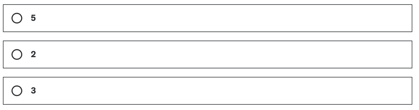
在初始化shader时候,创建一种特殊Buffer,其标注为 ComputeBufferType.IndirectArguments 。这种类型的缓冲区专门用于传递给 GPU,以便在 GPU 上执行间接绘制命令。这里的new ComputeBuffer 第一个参数是 1 ,表示一个args数组(一个数组有5个uint),不要理解错了。
ComputeBuffer argsBuffer;
...
argsBuffer = new ComputeBuffer(1, 5 * sizeof(uint), ComputeBufferType.IndirectArguments);
if (boidMesh != null)
{
    args[0] = (uint)boidMesh.GetIndexCount(0);
    args[1] = (uint)numOfBoids;
}
argsBuffer.SetData(args);
...
Graphics.DrawMeshInstancedIndirect(boidMesh, 0, boidMaterial, bounds, argsBuffer);
在上一章的基础上,个体的数据结构增加一个offset,在Compute Shader用于方向上的偏移。另外初始状态的方向用Slerp插值,70%保持原来的方向,30%随机。Slerp插值的结果是四元数,需要用四元数方法转换到欧拉角再传入构造函数。
public float noise_offset;
...
Quaternion rot = Quaternion.Slerp(transform.rotation, Random.rotation, 0.3f);
boidsArray[i] = new Boid(pos, rot.eulerAngles, offset);
将这个新的属性noise_offset传到Compute Shader后,计算范围是 [-1, 1] 的噪声值,应用到鸟的速度上。
float noise = clamp(noise1(time / 100.0 + boid.noise_offset), -1, 1) * 2.0 - 1.0;
float velocity = boidSpeed * (1.0 + noise * boidSpeedVariation);
然后稍微优化了一下算法。Compute Shader大体是没有区别的。
if (distance(boid_pos, boidsBuffer[i].position) < neighbourDistance)
{
    float3 tempBoid_position = boidsBuffer[i].position;
    float3 offset = boid.position - tempBoid_position;
    float dist = length(offset);
    if (dist<neighbourDistance){
        dist = max(dist, 0.000001);//Avoid division by zero
        separation += offset * (1.0/dist - 1.0/neighbourDistance);
    }
    alignment += boidsBuffer[i].direction;
    cohesion += tempBoid_position;
    nearbyCount += 1;
}
最大的不同在于Shader上。本节使用Surface Shader取代Frag。这个东西其实就是一个包装好的vertex and fragment shader。Unity已经完成了光照、阴影等一系列繁琐的工作。你依旧可以指定一个Vert。
写Shader制作材质的时候,需要对Instanced的物体做特别处理。因为普通的渲染对象,他们的位置、旋转和其他属性在Unity中是静态的。而对于当前要构建的实例化对象,其位置、旋转等参数时刻在变化,因此,在渲染管线中需要通过特殊的机制来动态设置每个实例化对象的位置和参数。当前的方法基于程序的实例化技术,可以一次性渲染所有的实例化对象,而不需要逐个绘制。也就是一次性批量渲染。
着色器应用instanced技术方法。实例化阶段是在vert之前执行。这样每个实例化的对象都有单独的旋转、位移和缩放等矩阵。
现在需要为每个实例化对象创建属于他们的旋转矩阵。从Buffer中我们拿到了Compute Shader计算后的鸟的基本信息(上一节中,该数据传回了CPU,这里直接传给Shader做实例化):

Shader里将Buffer传来的数据结构、相关操作用下面的宏包裹起来。
// .shader
#ifdef UNITY_PROCEDURAL_INSTANCING_ENABLED
struct Boid
{
float3 position;
float3 direction;
float noise_offset;
};
StructuredBuffer<Boid> boidsBuffer;
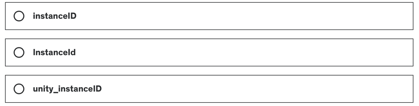
#endif由于我只在 C# 的 DrawMeshInstancedIndirect 的args[1]指定了需要实例化的数量(鸟的数量,也是Buffer的大小),因此直接使用unity_InstanceID索引访问Buffer就好了。
#pragma instancing_options procedural:setup
void setup()
{
    #ifdef UNITY_PROCEDURAL_INSTANCING_ENABLED
        _BoidPosition = boidsBuffer[unity_InstanceID].position;
        _Matrix = create_matrix(boidsBuffer[unity_InstanceID].position, boidsBuffer[unity_InstanceID].direction, float3(0.0, 1.0, 0.0));
    #endif
}这里的空间变换矩阵的计算涉及到Homogeneous Coordinates,可以去复习一下GAMES101的课程。点是(x,y,z,1),坐标是(x,y,z,0)。
如果使用仿射变换(Affine Transformations),代码是这样的:
void setup()
{
    #ifdef UNITY_PROCEDURAL_INSTANCING_ENABLED
    _BoidPosition = boidsBuffer[unity_InstanceID].position;
    _LookAtMatrix = look_at_matrix(boidsBuffer[unity_InstanceID].direction, float3(0.0, 1.0, 0.0));
    #endif
}
 void vert(inout appdata_full v, out Input data)
{
    UNITY_INITIALIZE_OUTPUT(Input, data);
    #ifdef UNITY_PROCEDURAL_INSTANCING_ENABLED
    v.vertex = mul(_LookAtMatrix, v.vertex);
    v.vertex.xyz += _BoidPosition;
    #endif
}
不够优雅,我们直接使用一个齐次坐标(Homogeneous Coordinates)。一个矩阵搞掂旋转平移缩放!
void setup()
{
    #ifdef UNITY_PROCEDURAL_INSTANCING_ENABLED
    _BoidPosition = boidsBuffer[unity_InstanceID].position;
    _Matrix = create_matrix(boidsBuffer[unity_InstanceID].position, boidsBuffer[unity_InstanceID].direction, float3(0.0, 1.0, 0.0));
    #endif
}
 void vert(inout appdata_full v, out Input data)
{
    UNITY_INITIALIZE_OUTPUT(Input, data);
    #ifdef UNITY_PROCEDURAL_INSTANCING_ENABLED
    v.vertex = mul(_Matrix, v.vertex);
    #endif
}
至此,就大功告成了!当前的帧率比上一节提升了将近一倍。


当前版本代码:
- Compute Shader:https://github.com/Remyuu/Unity-Compute-Shader-Learn/blob/L4_Instanced/Assets/Shaders/InstancedFlocking.compute
- CPU:https://github.com/Remyuu/Unity-Compute-Shader-Learn/blob/L4_Instanced/Assets/Scripts/InstancedFlocking.cs
- Shader:https://github.com/Remyuu/Unity-Compute-Shader-Learn/blob/L4_Instanced/Assets/Shaders/InstancedFlocking.shader
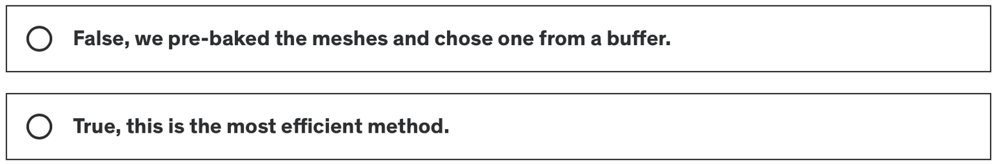
6. 应用蒙皮动画

本节要做的是,使用Animator组件,在实例化物体之前,将各个关键帧的Mesh抓取到Buffer当中。通过选取不同索引,得到不同姿势的Mesh。具体的骨骼动画制作不在本文讨论范围。
只需要在上一章的基础上修改代码,添加Animator等逻辑。我已经在下面写了注释,可以看看。
并且个体的数据结构有所更新:
struct Boid{
    float3 position;
    float3 direction;
    float noise_offset;
    float speed; // 暂时没啥用
    float frame; // 表示动画中的当前帧索引
    float3 padding; // 确保数据对齐
};
详细说说这里的对齐。一个数据结构中,数据的大小最好是16字节的整数倍。
- float3 position; (12字节)
- float3 direction; (12字节)
- float noise_offset; (4字节)
- float speed; (4字节)
- float frame; (4字节)
- float3 padding; (12字节)
如果没有Padding,大小是36字节,不是常见的对齐大小。加上Padding,对齐到48字节,完美!
private SkinnedMeshRenderer boidSMR; // 用于引用包含蒙皮网格的SkinnedMeshRenderer组件。
private Animator animator;
public AnimationClip animationClip; // 具体的动画剪辑,通常用于计算动画相关的参数。
private int numOfFrames; // 动画中的帧数,用于确定在GPU缓冲区中存储多少帧数据。
public float boidFrameSpeed = 10f; // 控制动画播放的速度。
MaterialPropertyBlock props; // 在不创建新材料实例的情况下传递参数给着色器。这意味着可以改变实例的材质属性(如颜色、光照系数等),而不会影响到使用相同材料的其他对象。
Mesh boidMesh; // 存储从SkinnedMeshRenderer烘焙出的网格数据。
...
void Start(){ // 这里首先初始化Boid数据,然后调用GenerateSkinnedAnimationForGPUBuffer来准备动画数据,最后调用InitShader来设置渲染所需的Shader参数。
    ...
    // This property block is used only for avoiding an instancing bug.
    props = new MaterialPropertyBlock();
    props.SetFloat("_UniqueID", Random.value);
    ...
    InitBoids();
    GenerateSkinnedAnimationForGPUBuffer();
    InitShader();
}
void InitShader(){ // 此方法配置Shader和材料属性,确保动画播放可以根据实例的不同阶段正确显示。frameInterpolation的启用或禁用决定了是否在动画帧之间进行插值,以获得更平滑的动画效果。
    ...
    if (boidMesh)//Set by the GenerateSkinnedAnimationForGPUBuffer
    ...
    shader.SetFloat("boidFrameSpeed", boidFrameSpeed);
    shader.SetInt("numOfFrames", numOfFrames);
    boidMaterial.SetInt("numOfFrames", numOfFrames);
    if (frameInterpolation && !boidMaterial.IsKeywordEnabled("FRAME_INTERPOLATION"))
    boidMaterial.EnableKeyword("FRAME_INTERPOLATION");
    if (!frameInterpolation && boidMaterial.IsKeywordEnabled("FRAME_INTERPOLATION"))
    boidMaterial.DisableKeyword("FRAME_INTERPOLATION");
}
void Update(){
    ...
    // 后面两个参数:
        // 1. 0: 参数缓冲区的偏移量,用于指定从哪里开始读取参数。
        // 2. props: 前面创建的 MaterialPropertyBlock,包含所有实例共享的属性。
    Graphics.DrawMeshInstancedIndirect( boidMesh, 0, boidMaterial, bounds, argsBuffer, 0, props);
}
void OnDestroy(){
    ...
    if (vertexAnimationBuffer != null) vertexAnimationBuffer.Release();
}
private void GenerateSkinnedAnimationForGPUBuffer()
{
    ... // 接下文
}
为了给Shader在不同的时间提供不同姿势的Mesh,因此在 GenerateSkinnedAnimationForGPUBuffer() 函数中,从 Animator 和 SkinnedMeshRenderer 中提取每一帧的网格顶点数据,然后将这些数据存储到GPU的 ComputeBuffer 中,以便在实例化渲染时使用。
通过GetCurrentAnimatorStateInfo获取当前动画层的状态信息,用于后续控制动画的精确播放。
numOfFrames 使用最接近动画长度和帧率乘积的二次幂来确定,可以优化GPU的内存访问。
然后创建一个ComputeBuffer来存储所有帧的所有顶点数据。vertexAnimationBuffer
在for循环中,烘焙所有动画帧。具体做法是,在每个sampleTime时间点播放并立即更新,然后烘焙当前动画帧的网格到bakedMesh中。并且提取刚刚烘焙好的Mesh顶点,更新到数组 vertexAnimationData 中,最后上传至GPU,结束。
// ...接上文
boidSMR = boidObject.GetComponentInChildren<SkinnedMeshRenderer>();
boidMesh = boidSMR.sharedMesh;
animator = boidObject.GetComponentInChildren<Animator>();
int iLayer = 0;
AnimatorStateInfo aniStateInfo = animator.GetCurrentAnimatorStateInfo(iLayer);
Mesh bakedMesh = new Mesh();
float sampleTime = 0;
float perFrameTime = 0;
numOfFrames = Mathf.ClosestPowerOfTwo((int)(animationClip.frameRate * animationClip.length));
perFrameTime = animationClip.length / numOfFrames;
var vertexCount = boidSMR.sharedMesh.vertexCount;
vertexAnimationBuffer = new ComputeBuffer(vertexCount * numOfFrames, 16);
Vector4[] vertexAnimationData = new Vector4[vertexCount * numOfFrames];
for (int i = 0; i < numOfFrames; i++)
{
    animator.Play(aniStateInfo.shortNameHash, iLayer, sampleTime);
    animator.Update(0f);
    boidSMR.BakeMesh(bakedMesh);
    for(int j = 0; j < vertexCount; j++)
    {
        Vector4 vertex = bakedMesh.vertices[j];
        vertex.w = 1;
        vertexAnimationData[(j * numOfFrames) +  i] = vertex;
    }
    sampleTime += perFrameTime;
}
vertexAnimationBuffer.SetData(vertexAnimationData);
boidMaterial.SetBuffer("vertexAnimation", vertexAnimationBuffer);
boidObject.SetActive(false);
在Compute Shader中,维护每一个个体数据结构中储存的帧变量。
boid.frame = boid.frame + velocity * deltaTime * boidFrameSpeed;
if (boid.frame >= numOfFrames) boid.frame -= numOfFrames;
在Shader中lerp不同帧的动画。左边是没有帧插值的,右边是插值后的,效果非常显著。

好的标题可以获得更多的推荐及关注者
void vert(inout appdata_custom v)
{
    #ifdef UNITY_PROCEDURAL_INSTANCING_ENABLED
        #ifdef FRAME_INTERPOLATION
            v.vertex = lerp(vertexAnimation[v.id * numOfFrames + _CurrentFrame], vertexAnimation[v.id * numOfFrames + _NextFrame], _FrameInterpolation);
        #else
            v.vertex = vertexAnimation[v.id * numOfFrames + _CurrentFrame];
        #endif
        v.vertex = mul(_Matrix, v.vertex);
    #endif
}
void setup()
{
    #ifdef UNITY_PROCEDURAL_INSTANCING_ENABLED
        _Matrix = create_matrix(boidsBuffer[unity_InstanceID].position, boidsBuffer[unity_InstanceID].direction, float3(0.0, 1.0, 0.0));
        _CurrentFrame = boidsBuffer[unity_InstanceID].frame;
        #ifdef FRAME_INTERPOLATION
            _NextFrame = _CurrentFrame + 1;
            if (_NextFrame >= numOfFrames) _NextFrame = 0;
            _FrameInterpolation = frac(boidsBuffer[unity_InstanceID].frame);
        #endif
    #endif
}
非常不容易,终于完整了。

完整工程链接:https://github.com/Remyuu/Unity-Compute-Shader-Learn/tree/L4_Skinned/Assets/Scripts
8. 总结/小测试
When rendering points which gives the best answer?

What are the three key steps in flocking?

When creating an arguments buffer for DrawMeshInstancedIndirect, how many uints are required?
We created the wing flapping by using a skinned mesh shader. True or False.
In a shader used by DrawMeshInstancedIndirect, which variable name gives the correct index for the instance?
References
- https://en.wikipedia.org/wiki/Boids
- Flocks, Herds, and Schools: A Distributed Behavioral Model
发表回复