


When it comes to fireworks shows, countless romantic scenes always come to mind.
Life is just about those few moments. I always feel that as long as I am under the brilliant fireworks, everything is worth it.
"Let's go, we have to watch the fireworks show." I will regret it for the rest of my life if I don't watch the winter fireworks at the foot of Mount Fuji.


I never understood why Eason Chan said, "If you want to have something, you must first understand how to accept losing it."
Trying to accept someone's departure is probably the norm.
After all, the results of things that we try our best are often not satisfactory. On the contrary, those things that go smoothly beyond expectations are the real goals that can be achieved.
If you are 100% sure about something, it becomes boring.
There are three things I don’t write in code
First: I don’t write something that cannot be copied, because why should I use someone else’s wheel if they have already written it?
Second: I won’t write if I’m not allowed to use Chatgpt as a “support”, because I already know the basics and there’s no point in writing.
Third: I don’t write about things that are too difficult, because I haven’t reached that level yet and can’t write clearly.


The state of modern people rushing for the bus is: the less anxious they are, the easier it is to miss it. The more anxious they are, the easier it is to miss it.
Only by being anxious at one moment and calm at another can you avoid missing out.
This time when we were trying to catch a bus in Kyoto, my friend and I were sprinting 100 meters one second, and the next second we were dominated by free magazines on the roadside for 3 minutes.
Even though I missed the bus, I didn't really regret it. It was just a little bit of a pity, after all, most things are not something I can decide, they are just what we are born with.


Why take Japan's night bus? Why not take the Shinkansen? Why not take a plane?
In order to watch this fireworks display, we had to stay in Kawaguchiko for a night.
In order to spend a more wonderful afternoon in Kyoto, taking a night bus is the most time-saving option.
A little-known fact is that the Shinkansen is more expensive than an airplane.
However, there are no airports in Kyoto and Kawaguchiko area, so the most convenient way to go from Kyoto to Mount Fuji is to take a night bus.

Before leaving for the station in the evening, I completed all the washing work in the public toilet of the hotel, and then had a good sleep after getting on the bus.
The night buses in Japan are quite comfortable. It may also be because I chose the most expensive one (only 36,800 yen for four people).
The seats are divided into three rows, with small curtains in between and charging ports. What else do you need a bicycle for?
The only thing I want to complain about is that the bus lights were not turned off until more than an hour after I got on the bus, and the driver was always broadcasting, but I couldn't hear what he was saying clearly. It was simply noise + light pollution.

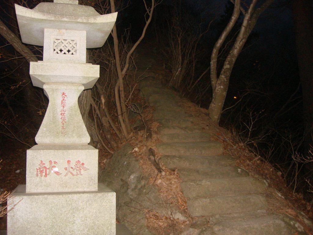
At about 7am, the bus was about to arrive at Fujiyoshida City. Passengers got off the bus one after another, and we were at the last stop, Kawaguchiko Station.

After getting off the bus, Mount Fuji is right in front of us.
But for some reason I remembered the street lights at dusk, the swaying treetops, the wandering figures, and you who once wanted to listen to "Under the Mount Fuji" with me. The meaning is not important, maybe I met the right person at the wrong time. Maybe the person is wrong and the time is right. Maybe both are wrong, or both are right, it doesn't matter. We live too hurriedly, and we no longer carefully question the distinction of emotions.
Mount Fuji is always there, you can see it but you can't move it.
I remembered a friend from the past. I met him in the school cafe when I was a freshman. This guy is different from us. He specializes in fortune-telling. He has his fixed seat in the cafe. He doesn't buy drinks, but just reads the Book of Changes. Every time I sit opposite him, I always feel that he is saying to those of us who are studying advanced mathematics: "Dachun, don't study advanced mathematics anymore, you can't learn it." Many times I wanted to ask him to help calculate how many points I can get in advanced mathematics at the end of this semester, but then I thought, anyway, if he continues like this, his advanced mathematics score will definitely not be higher than mine, so why bother relying on metaphysics.
Later, a strange video of a woman in red dancing outside a balcony fence and then falling from a building occurred in Hainan. It was said that she had gathered all the elements of gold, wood, water, fire and earth, and was performing some kind of evil sacrifice. I remembered this buddy, so I asked him to send it to him, but he said it was fake and no one would believe it.

A life with a purpose will lead you astray, a life without a purpose will not be wasted. The best time to plant a tree is ten years ago, the second best time is nine years ago.
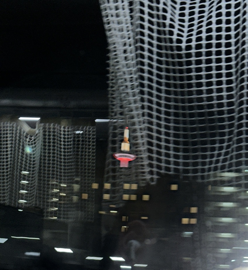
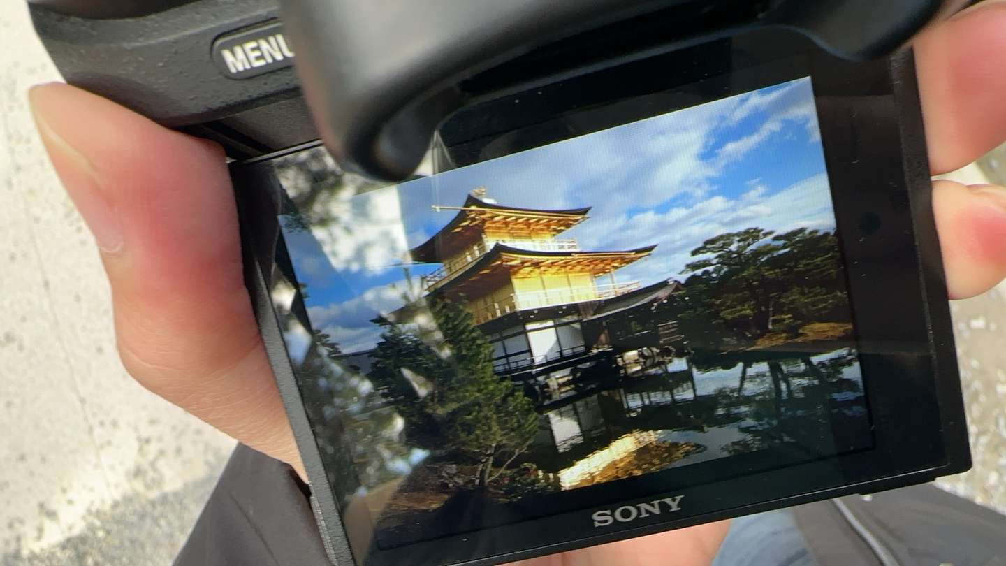
The most interesting part of traveling is its randomness. When I was storing my luggage at Kawaguchiko Station, I stumbled upon a buffet restaurant with a great view.


I love blues time. Whenever I see the blue sky, Debussy's Moonlight plays automatically in my mind.
In the trance of that moment, I couldn't help but take the photo in front of me. But suddenly I realized that I seemed to be dreaming, and everything in front of me disappeared with my screams at the top of my lungs. The ending of the people under Mount Fuji is always like this.

We followed the crowd all the way to Arakurayama Asama Park. The mountain was not high and was easy to climb.
He climbed up while eating strawberries.
It's a pity that there are no cherry blossoms in this season. After all, nothing is perfect and there are compromises everywhere.


This camera position should be considered a standard photo for tourists, and anyone can take a good-looking photo.
The weather was very good that day and we could see the whole view of Mount Fuji.
But the crowds were huge, and it must be one of the most crowded tourist spots in the Fuji area.


I really like the photo below, what do you think?


Unfortunately, the weather was not good. As soon as we descended the mountain, the clouds immediately covered Mount Fuji.
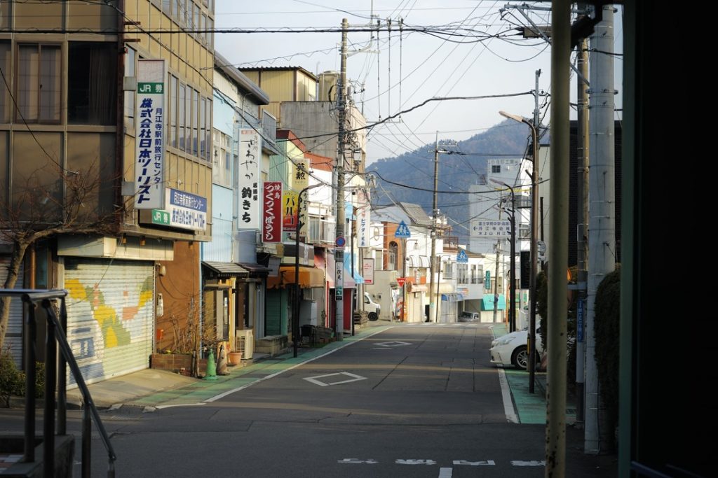
The photo shoot on the "Hommachi-dori" street that I had been longing for had to be abandoned.
I had to find a picture on Google Maps to make up for my regret.

Walking along Honmachi-dori towards Mount Fuji, my friend and I came to a small restaurant run by an old lady.
Before we entered, the boss was still hesitating whether to accept the guests as it was already past 2pm. Seeing that we were hungry and because we were Asian, he made an exception and accepted us as the last table, asking us to wait outside the door.
At this time, a group of European guys came in. Because of the language barrier, the boss probably meant that they would not be served, but neither side seemed to understand what he meant. A funny scene happened. I only heard the European guy say to me, "I hate racist, I don't Like her!", and then he left cursing. What a big misunderstanding.

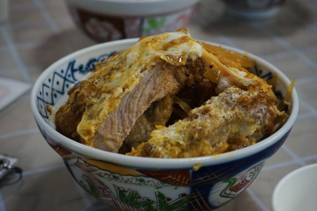
The portions are big, so you don't have to worry about not having enough to eat.
Udon noodles are free to refill, even if you order rice, you can ask the boss to give you free udon noodles.
Strolling through Fujiyoshida city.


Winter in Japan is not actually cold. Although the temperature on my phone is only 0 degrees, my heart is warm.
Fast forward to the time when I’m not afraid to wear shorts on snowy days.


Let’s talk about this fireworks show.
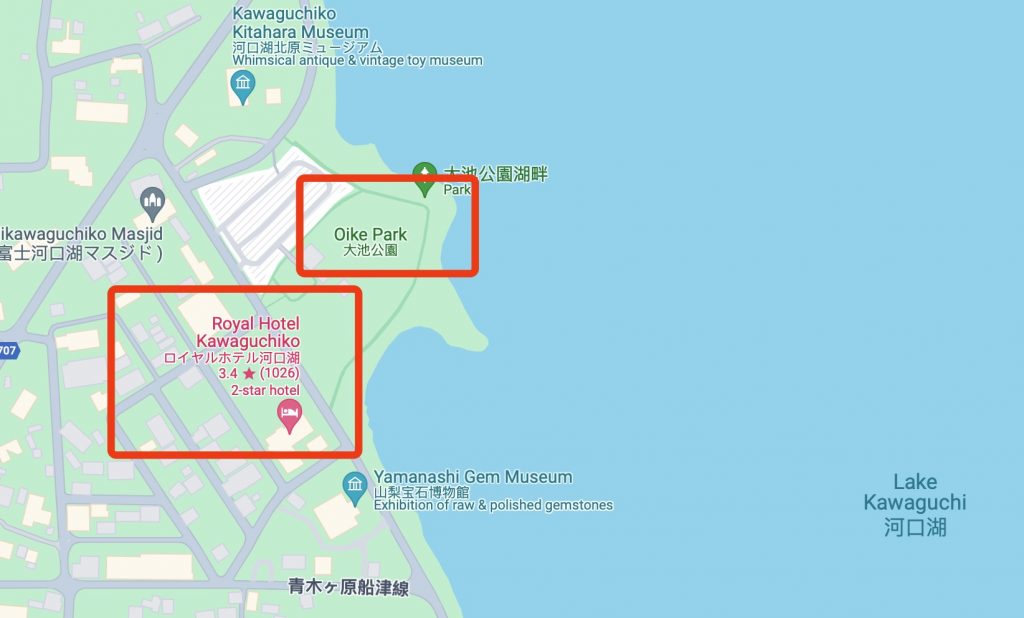
The location was Oike Park in Kawaguchiko. Thanks to my foresight, I booked a hot spring hotel just a stone's throw away from the fireworks launch site more than a month in advance. After the fireworks show, it was really pleasant to watch passers-by rushing back to Tokyo in a panic.
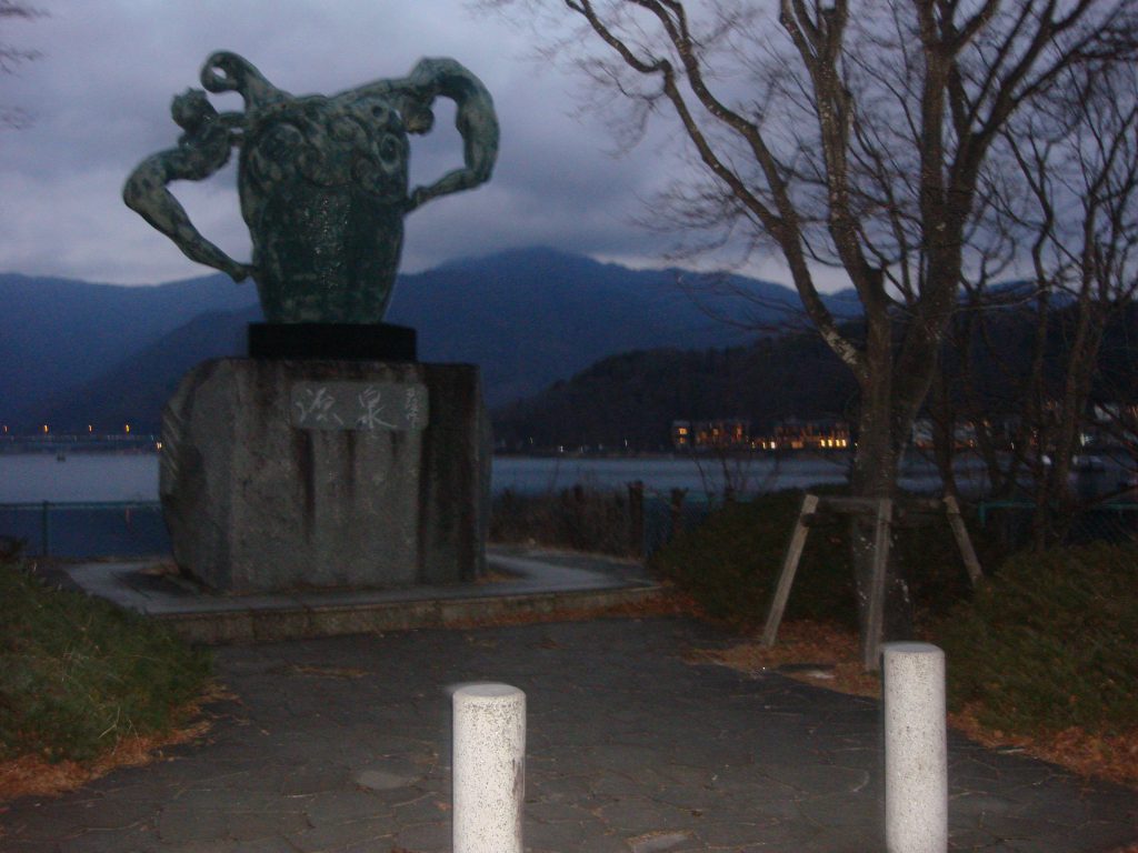
After returning to the hotel to freshen up, we went out for a bike ride around the lake.
There were still a few hours left before the fireworks, and the sky was gradually turning blue. I was so immersed in it that I forgot to take pictures. The following is a picture taken by my friend B using film. I like it very much, Instagram @dokidoki_yukina .


Fireworks are fleeting, yet they are eternal.


When I was a kid watching cartoons, my filter for fireworks shows was that the people under the fireworks shows would experience unforgettable moments in their lives.


When the last firework burst, nothing changed. The only thing that changed was the battery level of the camera and the feeling of hunger that followed.
Japanese instant noodles are really delicious, especially "Ichito", which I highly recommend. It's a pity that they are not available in Hong Kong and mainland China, so you can only buy them online from overseas.


Japanese hotels are quite interesting.
If I had to sum up Japan in one word, I would say: "Clean."
I saw a funny video on Instagram, where he spent 20,00$ on a plane to eat a convenience store rice ball worth 1$, and he ate it with gusto. The comment below said that the "dirtiest" food in Japan is cleaner than the "healthy food" in the United States.

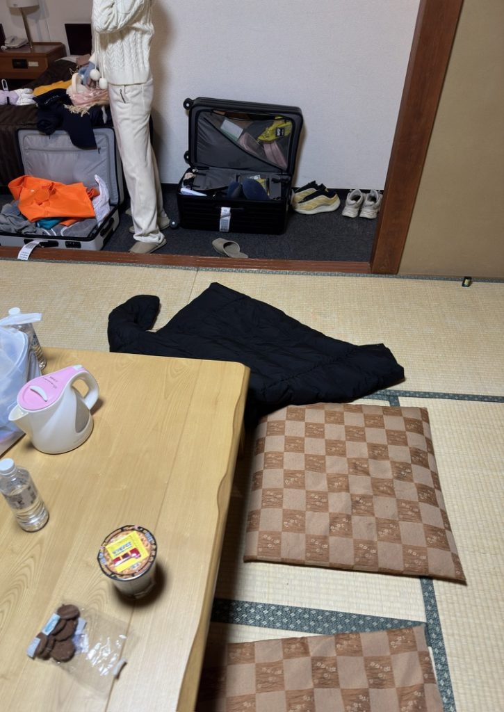
Another thing worth mentioning is that the prices of hotels in Japan are calculated based on the number of people.
Even if the room can accommodate three people, the price for two people and three people is completely different.
I saw some people discussing this issue on social platforms. What would happen if you secretly brought someone in to live with you?
Some people say that serious cases may result in deportation, but I don’t know if that’s true.
After all, the bespectacled guy must be unhappy because he didn't have to pay the hotel tax.
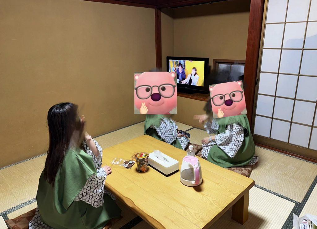
Kneeling on the tatami is comparable to military training.
Overall, I found that whether in a restaurant or a Japanese family, the scope of "sitting" is very large. If you have low blood sugar, you may need to pay special attention to this sitting.

This ramen instant noodles is really much more delicious than the ramen restaurants in China.
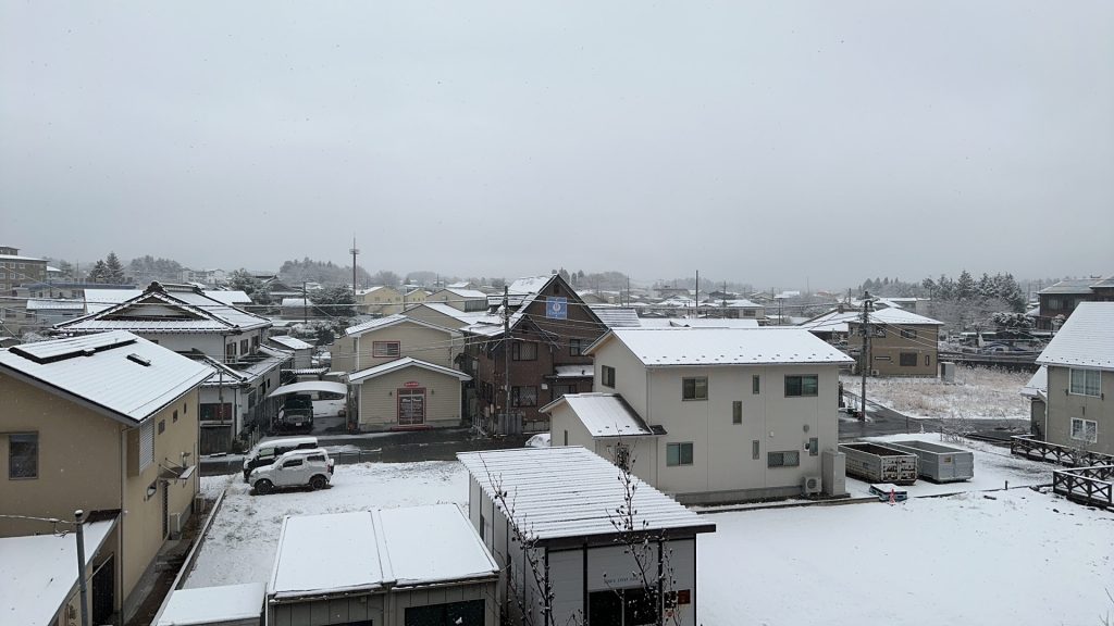
The next morning, friend B called us to get up early. I still remember this scene clearly, "Look, it's snowing outside the window!"

Procrastination.
Even though I knew I had to be at the station at 10 o'clock, I would have no time to take a walk if I didn't go out.
Come to think of it, it's the same in normal times. Even though I've already returned home exhausted and I want to take a shower, I still hold my phone and procrastinate for more than ten minutes.
Maybe the person on the other end of the phone feels the same way.
I may have blamed myself before, but in fact, it is wrong to criticize myself at every stage, let alone others. Everyone is going through different stages. When I was young, I felt that the sky would fall down after memorizing two pages of text. Now looking back, I can only laugh at myself for being too fragile.
In the end, we delayed until we really had to catch the bus before we went out to check out.


Next, we went to Tokyo and got lost in the bustling streets of rainy Tokyo with Black Widow in 2003.
Thank you for reading this, appreciate it.

Sound of sound
It's private
Magical sound
I'm thinking about this tonight
Soft and bright, light and sleep.
The heart is the wind and the consciousness is the consciousness...
Love
Waiting in a dream
The wound is healed by the feather root.
Today's でもあなただけなの
We will meet tonight
The beginning of the day is the same as the day of the first day.
I'm looking forward to it now
A miracle in the city
The stars are falling
Everyday
あの日からふたり citedき里そうとも…
Love
Who is this?
It’s time to leave
The one who promised in his heart is
I'm still here
Love
Waiting in a dream
The eye is closed and the current line is closed
Who has the best voice?
I love the difference between eyes
We will meet tonight
Tags: Getting Started/Shader/Tessellation Shader/Displacement Map/LOD/Smooth Outline/Early Culling
The word tessellation refers to a broad category of design activities, usually involving the arrangement of tiles of various geometric shapes next to each other to form a pattern on a flat surface. Its purpose can be artistic or practical, and many examples date back thousands of years. — Tessellation, Wikipedia, accessed July 2020.
This article mainly refers to:
Surface subdivision in game development is generally done in a triangleflat(or Quad) and then use the Displacement map to do vertex displacement, or use the Phong subdivision or PN triangles subdivision implemented in this article to do vertex displacement.
Phong subdivision does not need to know the adjacent topological information, only uses interpolation calculation, which is more efficient than PN triangles and other algorithms. Loop and Schaefer mentioned in GAMES101 use low-degree quadrilateral surfaces to approximate Catmull-Clark surfaces. The polygons input by these methods are replaced by a polynomial surface. The Phong subdivision in this article does not require any operation to correct additional geometric areas.
This chapter introduces the process of surface subdivision in the rendering pipeline.
The tessellation shader is located after the vertex shader, and the tessellation is divided into three steps: Hull, Tesselllator and Domain, among which Tessellator is not programmable.

The first step of tessellation is the tessellation control shader (also known as Tessellation Control Shader, TCS), which will output control points and tessellation factors. This stage mainly consists of two parallel functions: Hull Function and Patch Constant Function.

Both functions receive patches, which are a set of vertex indices. For example, a triangle uses three numbers to represent the vertex indices. One patch can form a fragment, for example, a triangle fragment is composed of three vertex indices.
Moreover, the Hull Function is executed once for each vertex, and the Path Constant Function is executed once for each Patch. The former outputs the modified control point data (usually including vertex position, possible normals, texture coordinates and other attributes), while the latter outputs the constant data related to the entire fragment, that is, the subdivision factor. The subdivision factor tells the next stage (the tessellator) how to subdivide each fragment.
In general, the Hull Function modifies each control point, while the Patch Constant Function determines the level of subdivision based on the distance from the camera.

Next comes the non-programmable stage, the tessellator. It receives the patch and the subdivision factor just obtained. The tessellator generates a barycentric coordinate for each vertex data.

Next comes the last step, the Domain Stage (also known as Tessellation Evaluation Shader, TES), which is programmable. This part consists of domain functions, which are executed once per vertex. It receives the barycentric coordinates and the results generated by the two functions in the Patch and Hull Stage. Most of the logic is written here. The most important thing is that you can reposition the vertices in this stage, which is the most important part of tessellation.

If there is a geometry shader, it will be executed after the Domain Stage. But if not, it will come to the rasterization stage.

In summary, the first thing is the vertex shader. The Hull stage accepts vertex data and decides how to subdivide the mesh. Then the tessellator stage processes the subdivided mesh, and finally the Domain stage outputs vertices for the fragment shader.
This chapter contains code analysis of Unity's surface subdivision, practical example effects display and an overview of the underlying principles.
First of all, the tessellation shader needs to use shader target 5.0.
HLSLPROGRAM
#Pragmas target 5.0 // 5.0 required for tessellation

#Pragmas vertex Vertex
#Pragmas hull Hull
#Pragmas domain Domain
#Pragmas fragment Fragment

ENDHLSLIn the classic process, the vertex shader converts the position and normal information into world space. Then the output result is passed to the Hull Stage. It should be noted that, unlike the vertex shader, the vertices of the Hull shader are represented by INTERNALTESSPOS semantics instead of POSITION semantics. The reason is that Hull does not need to output these vertex positions to the next rendering process, but for its own internal tessellation algorithm, so it will convert these vertices to a coordinate system that is more suitable for tessellation. In addition, developers can also distinguish more clearly.
struct Attributes {
    float3 positionOS : POSITION;
    float3 normalOS : NORMAL;
    UNITY_VERTEX_INPUT_INSTANCE_ID
};

struct TessellationControlPoint {
    float3 positionWS : INTERNAL LTESS POS;
    float3 normalWS : NORMAL;
    UNITY_VERTEX_INPUT_INSTANCE_ID
};

TessellationControlPoint Vertex(Attributes input) {
    TessellationControlPoint output;

    UNITY_SETUP_INSTANCE_ID(input);
    UNITY_TRANSFER_INSTANCE_ID(input, output);

    VertexPositionInputs posnInputs = GetVertexPositionInputs(input.positionOS);
    VertexNormalInputs normalInputs = GetVertexNormalInputs(input.normalOS);

    output.positionWS = posnInputs.positionWS;
    output.normalWS = normalInputs.normalWS;
    return output;
}
Below are some setting parameters for the Hull Shader.
The first line, domain, defines the domain type of the tessellation shader, which means that both the input and output are triangle primitives. You can choose tri (triangle), quad (quadrilateral), etc.
The second line outputcontrolpoints indicates the number of output control points, 3 corresponds to the three vertices of the triangle.
The third line outputtopology indicates the topological structure of the primitive after subdivision. triangle_cw means that the vertices of the output triangle are sorted clockwise. The correct order can ensure that the surface faces outward. triangle_cw (clockwise around the triangle), triangle_ccw (counterclockwise around the triangle), line (line segment)
The fourth line patchconstantfunc is another function of the Hull Stage, which outputs constant data such as subdivision factors. A patch is executed only once.
The fifth line, partitioning, specifies how to distribute additional vertices to the edges of the original Path primitive. This step can make the subdivision process smoother and more uniform. integer, fractional_even, fractional_odd.
The maxtessfactor in the sixth line represents the maximum subdivision factor. Limiting the maximum subdivision can control the rendering burden.
[domain("tri")]
[outputcontrolpoints(3)]
[outputtopology("triangle_cw")]
[patchconstantfunc("patchconstant")]
[partitioning("fractional_even")]
[maxtessfactor(64.0)]
In the Hull Shader, each control point will be called once independently, so this function will be executed the same number of control points. To know which vertex is currently being processed, we use the variable id with the semantics of SV_OutputControlPointID to determine. The function also passes in a special structure that can be used to easily access any control point in the Patch like an array.
TessellationControlPoint Hull(
    InputPatch<TessellationControlPoint, 3> patch, uint id : SV_OutputControlPointID) {
    TessellationControlPoint h;
    // Hull shader code here

    return patch[id];
}In addition to the Hull Shader, there is another function in the Hull Stage that runs in parallel, the patch constant function. The signature of this function is relatively simple. It inputs a patch and outputs the calculated subdivision factor. The output structure contains the tessellation factor specified for each edge of the triangle. These factors are identified by the special system value semantics SV_TessFactor. Each tessellation factor defines how many small segments the corresponding edge should be subdivided into, thereby affecting the density and details of the resulting mesh. Let's take a closer look at what this factor specifically contains.
struct TessellationFactors {
    float edge[3] : SV_TessFactor;
    float inside : SV_InsideTessFactor;
};
// The patch constant function runs once per triangle, or "patch"
// It runs in parallel to the hull function
TessellationFactors PatchConstantFunction(
    InputPatch<TessellationControlPoint, 3> patch) {
    UNITY_SETUP_INSTANCE_ID(patch[0]); // Set up instancing
    //Calculate tessellation factors
    TessellationFactors f;
    f.edge[0] = _FactorEdge1.x;
    f.edge[1] = _FactorEdge1.y;
    f.edge[2] = _FactorEdge1.z;
    f.inside = _FactorInside;
    return f;
}
First, there is an edge tessellation factor edge[3] in the TessellationFactors structure, marked as SV_TessFactor. When using triangles as the basic primitives for tessellation, each edge is defined as being located relative to the vertex with the same index. Specifically: edge 0 corresponds to vertex 1 and vertex 2. Edge 1 corresponds to vertex 2 and vertex 0. Edge 2 corresponds to vertex 0 and vertex 1. Why is this so? The intuitive explanation is that the index of the edge is the same as the index of the vertex it is not connected to. This helps to quickly identify and process the edges corresponding to specific vertices when writing shader code.
There is also a center tessellation factor inside labeled SV_InsideTessFactor. This factor directly changes the final tessellation pattern, and more essentially determines the number of edge subdivisions, which is used to control the subdivision density inside the triangle. Compared with the edge subdivision factor, the center tessellation factor controls how the inside of the triangle is further subdivided into smaller triangles, while the edge tessellation factor affects the number of edge subdivisions.
Patch Constant Function can also output other useful data, but it must be labeled with the correct semantics. For example, BEZIERPOS semantics is very useful and can represent float3 data. This semantics will be used later to output the control points of the smoothing algorithm based on the Bezier curve.
Next, we enter the Domain Stage. The Domain Function also has a Domain property, which should be the same as the output topology type of the Hull Function. In this example, it is set to a triangle. This function inputs the patch from the Hull Function, the output of the Patch Constant Function, and the most important vertex barycentric coordinates. The output structure is very similar to the output structure of the vertex shader, containing the position of the Clip space, as well as the lighting data required by the fragment shader.
It doesn’t matter if you don’t know what it is for now. Just read Chapter 4 of this article and then come back to study it.
Simply put, each new vertex that is subdivided will run this domain function.
struct Interpolators {
    float3 normalWS                 : TEXCOORD0;
    float3 positionWS               : TEXCOORD1;
    float4 positionCS               : SV_POSITION;
};

// Call this macro to interpolate between a triangle patch, passing the field name
#define BARYCENTRIC_INTERPOLATE(fieldName) \
        patch[0].fieldName * barycentricCoordinates.x + \
        patch[1].fieldName * barycentricCoordinates.y + \
        patch[2].fieldName * barycentricCoordinates.z

// The domain function runs once per vertex in the final, tessellated mesh
// Use it to reposition vertices and prepare for the fragment stage
[domain("tri")] // Signal we're inputting triangles
Interpolators Domain(
    TessellationFactors factors, //The output of the patch constant function
    OutputPatch<TessellationControlPoint, 3> patch, // The Input triangle
    float3 barycentricCoordinates : SV_DomainLocation) { // The barycentric coordinates of the vertex on the triangle

    Interpolators output;

    // Setup instancing and stereo support (for VR)
    UNITY_SETUP_INSTANCE_ID(patch[0]);
    UNITY_TRANSFER_INSTANCE_ID(patch[0], output);
    UNITY_INITIALIZE_VERTEX_OUTPUT_STEREO(output);

    float3 positionWS = BARYCENTRIC_INTERPOLATE(positionWS);
    float3 normalWS = BARYCENTRIC_INTERPOLATE(normalWS);

    output.positionCS = TransformWorldToHClip(positionWS);
    output.normalWS = normalWS;
    output.positionWS = positionWS;

    return output;
}
In this function, Unity will give us the subdivision factor, the three vertices of the patch, and the centroid coordinates of the current new vertex. We can use this data to do displacement processing, etc.
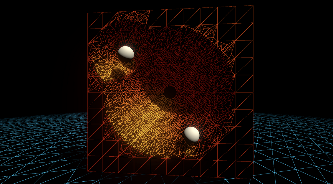
From thisLink Copy the code, then make the corresponding material and turn on the wireframe mode. We have only drawn vertices for the Mesh and have not applied any operations in the fragment shader, so it looks transparent.

If any component of the Edge Factor is set to 0 or less than 0, the Mesh will disappear completely. The following figure shows what it looks like after it disappears (the Unity editor's object border stroke is turned on). This feature is very important.

To put it bluntly, after these factors are set in the Hull Stage, they are simply and crudely written into the barycentric coordinates in the Tessellation Stage, such as edge factors and internal factors. (Assuming they are all tri, if it is quad, it is calculated using uv, which may be more complicated, I don't know) This simple and crude stage is not programmable.

Take "integer (uniform) cutting mode" as an example. (temporarily) [partitioning("integer")] The domain is all triangles [domain("tri")] The number of output vertices is also 3. [outputcontrolpoints(3)] And the output topology is a triangle clockwise. [outputtopology("triangle_cw")]
Modify the code to the following:
// .shader
_FactorEdge1("[Float3]Edge factors,[Float]Inside factor", Vector) = (1, 1, 1, 1) // -- Edited --

// .hlsl
float4 _FactorEdge1; // -- Edited --
...
f.edge[0] = _FactorEdge1.x;
f.edge[1] = _FactorEdge1.y; // -- Edited --
f.edge[2] = _FactorEdge1.z; // -- Edited --
f.inside = _FactorEdge1.w; // -- Edited --
There may be a problem here. Sometimes the compiler will split the Patch Constant Function and calculate each factor in parallel, which may cause some factors to be deleted, and the factors may be inexplicably equal to 0. The solution is to pack these factors into a vector so that the compiler will not use undefined quantities. The following is a simple reproduction of what may happen.
Modify the Path Constant Function as follows and open two new properties in the panel.
The modified code lines are commented out with // — Edited — .
// The patch constant function runs once per triangle, or "patch"
// It runs in parallel to the hull function
TessellationFactors PatchConstantFunction(
InputPatch<TessellationControlPoint, 3> patch) {
UNITY_SETUP_INSTANCE_ID(patch[0]); // Set up instancing
//Calculate tessellation factors
    TessellationFactors f;
    f.edge[0] = _FactorEdge1.x;
    f.edge[1] = _FactorEdge2; // -- Edited --
    f.edge[2] = _FactorEdge3; // -- Edited --
    f.inside = _FactorInside;
return f;
}
_FactorEdge2("Edge 2 factor", Float) = 1 // -- Edited --
_FactorEdge3("Edge 3 factor", Float) = 1 // -- Edited --It can be seen that the edge factors correspond approximately to the number of times the corresponding edge is split, and the internal factor corresponds to the complexity of the center.
The edge factor only affectsOriginal triangle edgeAs for the complex internal pattern, it is controlled by the internal factor Inside Factor and the division mode.
It should be noted that the surface subdivision in "integer cutting mode" is rounded up, for example, 2.1 is rounded up to 3.

One picture says it all.

Let's take the INTEGER mode as an example. The internal factor will only affect the complexity of the internal pattern. The specific influence is described in detail below.To summarize, the edge factor affects the triangular subdivision between the outermost layer and the first layer, the internal factor affects how many layers there are, and the division mode affects how each internal layer is subdivided.
Assuming that the Edge Factors are set to (2,3,4) and only the Insider Factor is modified, an interesting property can be observed: when the internal factor n is an even number, a vertex can be found whose coordinates are exactly at the centroid position (13,13,13).
Generally, it is good to set the edge factors to the same value. Here, different values are set, and the graph may be more confusing, but the most essential rules can be seen.

It can be further observed that the number of vertices on any edge closest to the outermost triangle has an equal relationship with the internal factor Inside Factor (n): n=Numpoint−1. That is, the number of vertices on this edge is always equal to the subdivision factor minus 1.

The number of vertices in each layer decreases by 1. That is, the first layer (not counting the outermost layer, as it will not be subdivided) will have n vertices, the second layer inward will have n−2 vertices, and so on.
Combining the above three observations, we can get a guess and conclusion(It’s useless, but I calculated it when I had nothing to do)The total number of internal vertices can be calculated using the formula, where n corresponds to the internal factor n-1. Note that the internal factor starts at 2: a2n=3n2a2n−1=3n(n−1)+1. This can be simplified and combined to: ak=−0.125(−1)k+0.75k2+0.125. The formula for all integer operations is as follows: ak=⌊−(−1)k+6k2+18⌋

The above only describes the simplest way to divide integers evenly, which uses integer multiples for subdivision. Let's talk about the other methods.Simply put, Fractional Odd and Fractional Even are advanced versions of Integer, but the former is an advanced version of Integer when it is an odd number, and the latter is an advanced version of Integer when it is an even number. The specific advancement is that the fractional part can be used to make the division no longer equal.

Fractional Odd: Inside Factor can be a fraction (not Ceil), and the denominator is an odd number. Note that the denominator here is actually the denominator represented by the barycentric coordinates of each vertex. The division method with an odd number as the denominator will definitely make a vertex fall on the barycentric coordinates of the triangle, while an even number will not.Kaios.

Fractional Even: Similar to fractional_odd, but with an even denominator. I'm not sure how to choose this.

Pow2 (power of 2): This mode only allows the use of powers of 2 (such as 1, 2, 4, 8, etc.) as subdivision levels. Generally used for texture mapping or shadow calculations.
Generating so many vertices will result in very bad performance! Therefore, some methods are needed to improve rendering efficiency. Although vertices outside the frustum will be culled before T rasterization, if unnecessary patches are culled in advance in TCS, the calculation pressure of the tessellation shader will be reduced.
If the tessellation factor is set to 0 in the Patch Constant Function, the tessellation generator will ignore the patch, which means that the culling here is for the entire patch, rather than the vertex-by-vertex culling in the frustum culling.
We test every point in the patch to see if they are out of view. To do this, transform every point in the patch into clip space. So we need to calculate the clip space coordinates of each point in the vertex shader and pass it to the Hull Stage. Use GetVertexPositionInputs to get what we want.
struct TessellationControlPoint {
    float4 positionCS : SV_POSITION; // -- Edited --
    ...
};

TessellationControlPoint Vertex(Attributes input) {
    TessellationControlPoint output;
    ...
    VertexPositionInputs posnInputs = GetVertexPositionInputs(input.positionOS);
    ...
    output.positionCS = posnInputs.positionCS; // -- Edited --
    ...
    return output;
}
Then write a test function above the Patch Constant Function to determine whether to cull the patch. Temporarily pass false here. The function passes in three points in the clipping space.
// Returns true if it should be clipped due to frustum or winding culling
bool ShouldClipPatch(float4 p0PositionCS, float4 p1PositionCS, float4 p2PositionCS) {
    return false;
}
Then write the IsOutOfBounds function to test whether a point is outside the bounds. The bounds can also be specified, and this method can be used in another function to determine whether a point is outside the view frustum.
// Returns true if the point is outside the bounds set by lower and higher
bool IsOutOfBounds(float3 p, float3 lower, float3 higher) {
    return p.x < lower.x || p.x > higher.x || p.y < lower.y || p.y > higher.y || p.z < lower.z || p.z > higher.z;
}

// Returns true if the given vertex is outside the camera fustum and should be culled
bool IsPointOutOfFrustum(float4 positionCS) {
    float3 culling = positionCS.xyz;
    float w = positionCS.w;
    // UNITY_RAW_FAR_CLIP_VALUE is either 0 or 1, depending on graphics API
    // Most use 0, however OpenGL uses 1
    float3 lowerBounds = float3(-w, -w, -w * UNITY_RAW_FAR_CLIP_VALUE);
    float3 higherBounds = float3(w, w, w);
    return IsOutOfBounds(culling, lowerBounds, higherBounds);
}
In Clip Space, the W component is the secondary coordinate that determines whether a point is in the view frustum. If xyz is outside the range [-w, w], these points will be culled because they are outside the view frustum. Different APIs have differentDepth of processingThere is a different logic on the , we need to pay attention when we use this component as the boundary. DirectX and Vulkan use the left-handed system, the Clip depth is [0, 1], so UNITY_RAW_FAR_CLIP_VALUE is 0. OpenGL is a right-handed system, the Clip depth range is [-1, 1], and UNITY_RAW_FAR_CLIP_VALUE is 1.
After preparing these, you can determine whether a patch needs to be culled. Go back to the function at the beginning and determine whether all the points of a patch need to be culled.
// Returns true if it should be clipped due to frustum or winding culling
bool ShouldClipPatch(float4 p0PositionCS, float4 p1PositionCS, float4 p2PositionCS) {
    bool allOutside = IsPointOutOfFrustum(p0PositionCS) &&
        IsPointOutOfFrustum(p1PositionCS) &&
        IsPointOutOfFrustum(p2PositionCS); // -- Edited --
    return allOutside; // -- Edited --
}In addition to frustum culling, patches can also undergo backface culling, using the normal vector to determine whether a patch needs to be culled.

The normal vector is obtained by taking the cross product of two vectors. Since we are currently in Clip space, we need to do a perspective division to get NDC, which should be in the range of [-1,1]. The reason for converting to NDC is that the position in Clip space is nonlinear, which may cause the position of the vertex to be distorted. Converting to a linear space like NDC can more accurately determine the front and back relationship of the vertices.
// Returns true if the points in this triangle are wound counter-clockwise
bool ShouldBackFaceCull(float4 p0PositionCS, float4 p1PositionCS, float4 p2PositionCS) {
    float3 point0 = p0PositionCS.xyz / p0PositionCS.w;
    float3 point1 = p1PositionCS.xyz / p1PositionCS.w;
    float3 point2 = p2PositionCS.xyz / p2PositionCS.w;
    float3 normal = cross(point1 - point0, point2 - point0);
    return dot(normal, float3(0, 0, 1)) < 0;
}
The above code still has a cross-platform problem. The viewing direction is different in different APIs, so modify the code.
// In clip space, the view direction is float3(0, 0, 1), so we can just test the z coord
#if UNITY_REVERSED_Z
    return cross(point1 - point0, point2 - point0).z < 0;
#else // In OpenGL, the test is reversed
    return cross(point1 - point0, point2 - point0).z > 0;
#endif
Finally, add the function you just wrote to ShouldClipPatch to determine backface culling.
// Returns true if it should be clipped due to frustum or winding culling
bool ShouldClipPatch(float4 p0PositionCS, float4 p1PositionCS, float4 p2PositionCS) {
    bool allOutside = IsPointOutOfFrustum(p0PositionCS) &&
        IsPointOutOfFrustum(p1PositionCS) &&
        IsPointOutOfFrustum(p2PositionCS);
    return allOutside || ShouldBackFaceCull(p0PositionCS, p1PositionCS, p2PositionCS); // -- Edited --
}
Then set the vertex factor of the patch to be culled to 0 in PatchConstantFunction.
...
if (ShouldClipPatch(patch[0].positionCS, patch[1].positionCS, patch[2].positionCS)) {
        f.edge[0] = f.edge[1] = f.edge[2] = f.inside = 0; // Cull the patch
}
...You may want to verify the correctness of the code, or there may be some unexpected exclusions. In this case, adding a tolerance is a flexible approach.
The first is the frustum culling tolerance. If the tolerance is positive, the culling boundaries will be expanded so that some objects near the edge of the frustum will not be culled even if they are partially out of bounds. This method can reduce the frequent changes in culling state due to small perspective changes or object dynamics.
// Returns true if the given vertex is outside the camera fustum and should be culled
bool IsPointOutOfFrustum(float4 positionCS, float tolerance) {
    float3 culling = positionCS.xyz;
    float w = positionCS.w;
    // UNITY_RAW_FAR_CLIP_VALUE is either 0 or 1, depending on graphics API
    // Most use 0, however OpenGL uses 1
    float3 lowerBounds = float3(-w - tolerance, -w - tolerance, -w * UNITY_RAW_FAR_CLIP_VALUE - tolerance);
    float3 higherBounds = float3(w + tolerance, w + tolerance, w + tolerance);
    return IsOutOfBounds(culling, lowerBounds, higherBounds);
}
Next, backface culling is adjusted. In practice, this is done by comparing to a tolerance instead of zero to avoid issues with numerical precision. If the dot product result is less than some small positive value (the tolerance) instead of being strictly less than zero, then the primitive is considered a backface. This approach provides an additional buffer, ensuring that only explicitly backface primitives are culled.
// Returns true if the points in this triangle are wound counter-clockwise
bool ShouldBackFaceCull(float4 p0PositionCS, float4 p1PositionCS, float4 p2PositionCS, float tolerance) {
    float3 point0 = p0PositionCS.xyz / p0PositionCS.w;
    float3 point1 = p1PositionCS.xyz / p1PositionCS.w;
    float3 point2 = p2PositionCS.xyz / p2PositionCS.w;
    // In clip space, the view direction is float3(0, 0, 1), so we can just test the z coord
#if UNITY_REVERSED_Z
    return cross(point1 - point0, point2 - point0).z < -tolerance;
#else // In OpenGL, the test is reversed
    return cross(point1 - point0, point2 - point0).z > tolerance;
#endif
}
It is possible to expose a Range in the Material Panel.
// .shader
Properties{
    _tolerance("_tolerance",Range(-0.002,0.001)) = 0
    ...
}
// .hlsl
float _tolerance;
...
// Returns true if it should be clipped due to frustum or winding culling
bool ShouldClipPatch(float4 p0PositionCS, float4 p1PositionCS, float4 p2PositionCS) {
    bool allOutside = IsPointOutOfFrustum(p0PositionCS, _tolerance) &&
        IsPointOutOfFrustum(p1PositionCS, _tolerance) &&
        IsPointOutOfFrustum(p2PositionCS, _tolerance); // -- Edited --
    return allOutside || ShouldBackFaceCull(p0PositionCS, p1PositionCS, p2PositionCS,_tolerance); // -- Edited --
}
So far, our algorithm has subdivided all surfaces indiscriminately. However, in a complex Mesh, there may be large and small faces.Uneven Mesh AreaThe large face is more obvious visually due to its large area, and more subdivisions are needed to ensure the smoothness and details of the surface. The small face is small in area, so you can consider reducing the subdivision level of this part, which will not have a big impact on the visual effect. Dynamically changing the factor according to the length change is a common method. Set an algorithm to give faces with longer side lengths a higher subdivision factor.
In addition to the large and small faces of the Mesh itself,The distance between the camera and the patchIt can also be used as a factor to dynamically change the factor. Objects that are farther away from the camera can have a lower tessellation factor because they occupy fewer pixels on the screen.The user’s viewing angle and gaze direction, you can prioritize subdividing faces that face the camera, and reduce the level of subdivision for faces that face away from the camera or to the sides.
Get the distance between two vertices. The larger the distance, the larger the subdivision factor. The scale is exposed in the control panel and set to [0,1]. When the scale is 1, the subdivision factor is directly contributed by the distance between the two points. The closer the scale is to 0, the larger the subdivision factor. In addition, an initial value bias is added. Finally, let it take a number of 1 or above to ensure accuracy.
//Calculate the tessellation factor for an edge
float EdgeTessellationFactor(float scale, float bias, float3 p0PositionWS, float3 p1PositionWS) {
    float factor = distance(p0PositionWS, p1PositionWS) / scale;

    return max(1, factor + bias);
}
Then modify the material panel and Patch Constant Function. Generally speaking, the average value of the edge subdivision factor is used as the internal subdivision factor, which will give a more consistent visual effect.
// .shader
Properties{
    ...
    _TessellationBias("_TessellationBias", Range(-1,5)) = 1
     _TessellationFactor("_TessellationFactor", Range(0,1)) = 0
}

// .hlsl

f.edge[0] = EdgeTessellationFactor(_TessellationFactor, _TessellationBias, patch[1].positionWS, patch[2].positionWS);
f.edge[1] = EdgeTessellationFactor(_TessellationFactor, _TessellationBias, patch[2].positionWS, patch[0].positionWS);
f.edge[2] = EdgeTessellationFactor(_TessellationFactor, _TessellationBias, patch[0].positionWS, patch[1].positionWS);
f.inside = (f.edge[0] + f.edge[1] + f.edge[2]) / 3.0;
The degree of subdivision of fragments of different sizes will change dynamically, and the effect is as follows.

By the way, if you find that your internal factor pattern is very strange, this may be caused by the compiler. Try to modify the internal factor code to the following to solve it.
f.inside = ( // If the compiler doesn't play nice...
  EdgeTessellationFactor(_TessellationFactor, _TessellationBias, patch[1].positionWS, patch[2].positionWS) +
  EdgeTessellationFactor(_TessellationFactor, _TessellationBias, patch[2].positionWS, patch[0].positionWS) +
  EdgeTessellationFactor(_TessellationFactor, _TessellationBias, patch[0].positionWS, patch[1].positionWS)
) / 3.0;Next, we need to determine the camera distance. We can directlyUse screen space distance to adjust the subdivision level, which perfectly solves the problem of large and small surfaces + screen distance at the same time!
Since we already have the data in Clip space, and since screen space is very similar to NDC space, we only need to convert it to NDC, that is, do a perspective division.
float EdgeTessellationFactor(float scale, float bias, float3 p0PositionWS, float4 p0PositionCS, float3 p1PositionWS, float4 p1PositionCS) {
    float factor = distance(p0PositionCS.xyz / p0PositionCS.w, p1PositionCS.xyz / p1PositionCS.w) / scale;

    return max(1, factor + bias);
}
Next, pass the Clip space coordinates into the Patch Constant Function.
f.edge[0] = EdgeTessellationFactor(_TessellationFactor, _TessellationBias,
  patch[1].positionWS, patch[1].positionCS, patch[2].positionWS, patch[2].positionCS);
f.edge[1] = EdgeTessellationFactor(_TessellationFactor, _TessellationBias,
  patch[2].positionWS, patch[2].positionCS, patch[0].positionWS, patch[0].positionCS);
f.edge[2] = EdgeTessellationFactor(_TessellationFactor, _TessellationBias,
  patch[0].positionWS, patch[0].positionCS, patch[1].positionWS, patch[1].positionCS);
f.inside = (f.edge[0] + f.edge[1] + f.edge[2]) / 3.0;
The current effect is quite good, and the level of subdivision changes dynamically as the camera distance (screen space distance) changes. If you use a subdivision mode other than INTEGER, you will get a more consistent effect.

There are still some areas that can be improved. For example, the unit of the scaling factor. Just now we controlled it to [0,1], which is not very suitable for us to adjust. We multiply it by the screen resolution and change the scaling factor range to [0,1080], which is more convenient for us to adjust. Then modify the material panel properties. Now it is a ratio in pixels.
// .hlsl
float factor = distance(p0PositionCS.xyz / p0PositionCS.w, p1PositionCS.xyz / p1PositionCS.w) * _ScreenParams.y / scale;

// .shader
_TessellationFactor("_TessellationFactor",Range(0,1080)) = 320
How do we use camera distance scaling? It's very simple. We calculate the ratio of the distance between two points and the distance between the midpoint of the two vertices and the camera position. The larger the ratio, the larger the space occupied on the screen, and the more subdivision is needed.
// .hlsl
float EdgeTessellationFactor(float scale, float bias, float3 p0PositionWS, float3 p1PositionWS) {
    float length = distance(p0PositionWS, p1PositionWS);
    float distanceToCamera = distance(GetCameraPositionWS(), (p0PositionWS + p1PositionWS) * 0.5);
    float factor = length / (scale * distanceToCamera * distanceToCamera);
    return max(1, factor + bias);
}
...
        f.edge[0] = EdgeTessellationFactor(_TessellationFactor, _TessellationBias, patch[1].positionWS, patch[2].positionWS);
        f.edge[1] = EdgeTessellationFactor(_TessellationFactor, _TessellationBias, patch[2].positionWS, patch[0].positionWS);
        f.edge[2] = EdgeTessellationFactor(_TessellationFactor, _TessellationBias, patch[0].positionWS, patch[1].positionWS);

// .shader
_TessellationFactor("_TessellationFactor",Range(0, 1)) = 0.02
Note that the scaling factor is no longer in pixels, but in the original [0,1] unit. Because screen pixels are not very meaningful in this method, they are not used. And the world coordinates are used again.
The results of screen space subdivision scaling and camera distance subdivision scaling are similar. Generally, a macro can be opened to switch the modes of the above dynamic factors. Here, it is left to the reader to complete.
In the previous section, we used different strategies to guess the appropriate subdivision factors. If we know exactly how the mesh should be subdivided, we can store the coefficients of these subdivision factors in the mesh. Since the coefficient only needs a float, only one color channel is needed. The following is a pseudo code, just give it a try.
float EdgeTessellationFactor(float scale, float bias, float multiplier) {
    ...
    return max(1, (factor + bias) * multiplier);
}

...
// PCF()
[unroll] for (int i = 0; i < 3; i++) {
    multipliers[i] = patch[i].color.g;
}
//Calculate tessellation factors
f.edge[0] = EdgeTessellationFactor(_TessellationFactor, _TessellationBias, (multipliers[1] + multipliers[2]) / 2);
It is quite cool to combine the Signed Distance Field (SDF) to control the tessellation factor. Of course, this section does not involve the generation of SDF, assuming that it can be directly obtained through the ready-made function CalculateSDFDistance.
For a given Mesh, use CalculateSDFDistance to calculate the distance from each vertex in each patch to the shape represented by the SDF (such as a sphere). After obtaining the distance, evaluate the subdivision requirements of the patch and perform subdivision.
TessellationFactors PatchConstantFunction(
    InputPatch<TessellationControlPoint, 3> patch) {
    float multipliers[3];

    // Loop through each vertex
    [unroll] for (int i = 0; i < 3; i++) {
        // Calculate the distance from each vertex to the SDF surface
        float sdfDistance = CalculateSDFDistance(patch[i].positionWS);

        // Adjust subdivision factor based on SDF distance
        if (sdfDistance < _TessellationDistanceThreshold) {
            multipliers[i] = lerp(_MinTessellationFactor, _MaxTessellationFactor, (1 - sdfDistance / _TessellationDistanceThreshold));
        } else {
            multipliers[i] = _MinTessellationFactor;
        }
    }

    // Calculate the final subdivision factor
    TessellationFactors f;
    f.Edge[0] = max(multipliers[0], multipliers[1]);
    f.Edge[1] = max(multipliers[1], multipliers[2]);
    f.Edge[2] = max(multipliers[2], multipliers[0]);
    f.Inside = (multipliers[0] + multipliers[1] + multipliers[2]) / 3;

    return f;
}
I don't know how to implement it specifically, so I'll try to understand it first.

The easiest way to add details to a mesh is to use various high-resolution textures. However, the bottom line is that adding more vertices to a mesh is better than increasing the texture resolution. For example, a normal map can change the direction of each fragment's normal, but it does not change the geometry. Even a 128K texture cannot eliminate aliasing and pointy edges.

Therefore, we need to tessellate the surface and then offset the vertices. All the tessellation operations just mentioned are operated on the plane where the patch is located. If we want to bend these vertices, one of the simplest operations is Phong tessellation.
First, the original paper is attached. https://perso.telecom-paristech.fr/boubek/papers/PhongTessellation/PhongTessellation.pdf
Phong shading should be familiar to you. It is a technique that uses linear interpolation of normal vectors to obtain smooth shading. Phong subdivision is inspired by Phong shading and extends the concept of Phong shading to the spatial domain.
The core idea of Phong subdivision is to use the vertex normals of each corner of the triangle to affect the position of new vertices during the subdivision process, thereby creating a curved surface instead of a flat surface.
It is worth noting that many tutorials here use triangle corner to represent vertices. I think they are all the same, so I will still use vertices in this article.
First, in the Domain function, Unity will give us the centroid coordinates of the new vertex we need to process. Suppose we are currently processing (13,13,13).

Each vertex of a patch has a normal. Imagine a tangent plane emanating from each vertex, perpendicular to the respective normal vector.


Then project the current vertex onto these three tangent planes respectively.

Describe it in mathematical language. P′=P−((P−V)⋅N)N
in :
Get three $P'$.


The three points projected on the three tangent planes are re-formed into a new triangle, and then the centroid coordinates of the current vertex are applied to the new triangle to calculate the new point.

//Calculate Phong projection offset
float3 PhongProjectedPosition(float3 flatPositionWS, float3 cornerPositionWS, float3 normalWS) {
    return flatPositionWS - dot(flatPositionWS - cornerPositionWS, normalWS) * normalWS;
}

// Apply Phong smoothing
float3 CalculatePhongPosition(float3 bary, float3 p0PositionWS, float3 p0NormalWS,
    float3 p1PositionWS, float3 p1NormalWS, float3 p2PositionWS, float3 p2NormalWS) {
    float3 smoothedPositionWS =
        bary.x * PhongProjectedPosition(flatPositionWS, p0PositionWS, p0NormalWS) +
        bary.y * PhongProjectedPosition(flatPositionWS, p1PositionWS, p1NormalWS) +
        bary.z * PhongProjectedPosition(flatPositionWS, p2PositionWS, p2NormalWS);
    return smoothedPositionWS;
}

// The domain function runs once per vertex in the final, tessellated mesh
// Use it to reposition vertices and prepare for the fragment stage
[domain("tri")] // Signal we're inputting triangles
Interpolators Domain(
    TessellationFactors factors, //The output of the patch constant function
    OutputPatch<TessellationControlPoint, 3> patch, // The Input triangle
    float3 barycentricCoordinates : SV_DomainLocation) { // The barycentric coordinates of the vertex on the triangle

    Interpolators output;
    ...
    float3 positionWS = CalculatePhongPosition(barycentricCoordinates,
      patch[0].positionWS, patch[0].normalWS,
      patch[1].positionWS, patch[1].normalWS,
      patch[2].positionWS, patch[2].normalWS);
    float3 normalWS = BARYCENTRIC_INTERPOLATE(normalWS);
    float3 tangentWS = BARYCENTRIC_INTERPOLATE(tangentWS.xyz);
    ...
    output.positionCS = TransformWorldToHClip(positionWS);
    output.normalWS = normalWS;
    output.positionWS = positionWS;
    output.tangentWS = float4(tangentWS, patch[0].tangentWS.w);
    ...
}
Note that we need to add the normal vector here, and then write it into Vertex and Domain. Then write a function to calculate the coordinates of the center of gravity of $P'$.
struct Attributes {
    ...
    float4 tangentOS : TANGENT;
};
struct TessellationControlPoint {
    ...
    float4 tangentWS : TANGENT;
};
struct Interpolators {
    ...
    float4 tangentWS : TANGENT;
};
TessellationControlPoint Vertex(Attributes input) {
    TessellationControlPoint output;
    ...
    // .....The last one is the symbol coefficient
    output.tangentWS = float4(normalInputs.tangentWS, input.tangentOS.w); // tangent.w contains bitangent multiplier
}
// Barycentric interpolation as a function
float3 BarycentricInterpolate(float3 bary, float3 a, float3 b, float3 c) {
    return bary.x * a + bary.y * b + bary.z * c;
}
In the original Phong subdivision paper, an α factor was added to control the degree of curvature. The original author recommends setting this value globally to three-quarters for the best visual effect. Expanding the algorithm with the α factor can produce a quadratic Bezier curve, which does not provide an inflection point but is sufficient for practical development.

First, let’s look at the formula in the original paper.

Essentially, it controls the degree of interpolation. A quantitative analysis shows that when α=0, all vertices are on the original plane, which is equivalent to no displacement. When α=1, the new vertices are completely dependent on the Phong subdivision bending vertices. Of course, you can also try values less than zero or greater than one, and the effect is also quite interesting. ~~It doesn’t matter if you don’t understand the mathematical formulas in the original text. I will just use a lerp and make a random interpolation.~~
// Apply Phong smoothing
float3 CalculatePhongPosition(float3 bary, float smoothing, float3 p0PositionWS, float3 p0NormalWS,
    float3 p1PositionWS, float3 p1NormalWS, float3 p2PositionWS, float3 p2NormalWS) {
    float3 flatPositionWS = BarycentricInterpolate(bary, p0PositionWS, p1PositionWS, p2PositionWS);
    float3 smoothedPositionWS =
        bary.x * PhongProjectedPosition(flatPositionWS, p0PositionWS, p0NormalWS) +
        bary.y * PhongProjectedPosition(flatPositionWS, p1PositionWS, p1NormalWS) +
        bary.z * PhongProjectedPosition(flatPositionWS, p2PositionWS, p2NormalWS);
    return lerp(flatPositionWS, smoothedPositionWS, smoothing);
}
Don't forget to expose in the material panel.
// .shader
_TessellationSmoothing("_TessellationSmoothing", Range(0,1)) = 0.5

// .hlsl
float _TessellationSmoothing;


Interpolators Domain( .... ) {
    ...
    float smoothing = _TessellationSmoothing;
    float3 positionWS = CalculatePhongPosition(barycentricCoordinates, smoothing,
      patch[0].positionWS, patch[0].normalWS,
      patch[1].positionWS, patch[1].normalWS,
      patch[2].positionWS, patch[2].normalWS);
    ...
}
It is important to note that some models require some modification. If the edges of the model are very sharp, it means that the normal of this vertex is almost parallel to the normal of the face. In Phong Tessellation, this will cause the projection of the vertex on the tangent plane to be very close to the original vertex position, thus reducing the impact of subdivision.
To solve this problem, you can add more geometric details by performing what is called "adding loop edges" or "loop cuts" in the modeling software. Insert additional edge loops near the edges of the original model to increase the subdivision density. The specific operation will not be expanded here.
In general, the effect and performance of Phong subdivision are relatively good. However, if you want a higher quality smoothing effect, you can consider PN triangles. This technology is based on the curved triangle of Bezier curve.
First, here is the original paper. http://alex.vlachos.com/graphics/CurvedPNTriangles.pdf
PN Triangles does not require information about neighboring triangles and is less expensive. The PN Triangles algorithm only requires the positions and normals of the three vertices in the patch. The rest of the data can be calculated. Note that all data is in barycentric coordinates.
In the PN algorithm, 10 control points need to be calculated for surface subdivision, as shown in the figure below. Three triangle vertices, a centroid, and three pairs of control points on the edges constitute all the control points. The calculated Bezier curve control points will be passed to the Domain. Since the control points of each triangle patch are consistent, it is very appropriate to place the step of calculating the control points in the Patch Constant Function.

The calculation method in the paper is as follows:
$$
\begin{aligned}
b_{300} & =P_1 \
b_{030} & =P_2 \
b_{003} & =P_3 \
w_{ij} & =\left(P_j-P_i\right) \cdot N_i \in \mathbf{R} \quad \text { here ' } \cdot \text { ' is the scalar product, } \
b_{210} & =\left(2 P_1+P_2-w_{12} N_1\right) / 3 \
b_{120} & =\left(2 P_2+P_1-w_{21} N_2\right) / 3 \
b_{021} & =\left(2 P_2+P_3-w_{23} N_2\right) / 3 \
b_{012} & =\left(2 P_3+P_2-w_{32} N_3\right) / 3 \
b_{102} & =\left(2 P_3+P_1-w_{31} N_3\right) / 3, \
b_{201} & =\left(2 P_1+P_3-w_{13} N_1\right) / 3, \
E & =\left(b_{210}+b_{120}+b_{021}+b_{012}+b_{102}+b_{201}\right) / 6 \
V & =\left(P_1+P_2+P_3\right) / 3, \
b_{111} & =E+(EV) / 2 .
\end{aligned}
$$
Each edge of the formula $w_{ij}$ is calculated twice, so a total of 6 times. For example, the meaning of $w_{1 2}$ is the projection length of the vector from $P_1$ to $P_2$ in the normal direction of $P_1$. Multiplying it by the corresponding normal direction means that the projection vector is $w$ in length.
Let's take the calculation of the factor close to $P_1$ as an example. The weight of the current position point should be larger. Multiplying it by $2$ makes the calculated control point closer to the current vertex. The reason for subtracting the projection vector is to correct the error caused by the position of $P_2$ not being on the plane defined by the $P_1$ normal. Make the triangle plane more consistent and reduce the distortion effect. Finally, divide by 3 for standardization.
Next, calculate the average Bezier control point $E$, which represents the average position of the six control points. This average position represents the concentration trend of the boundary control points. Then calculate the average position of the triangle vertices. Then find the midpoint of these two average positions and add it to the Bezier average control point. This is the tenth parameter required in the end.
To summarize, the first three are the positions of the triangle vertices (so they don't need to be written in the structure), six are calculated by weight, and the last one is the average of the previous calculations. The code is very simple to write.
struct TessellationFactors {
    float edge[3] : SV_TessFactor;
    float inside : SV_InsideTessFactor;
    float3 bezierPoints[7] : BEZIERPOS;
};

//Bezier control point calculations
float3 CalculateBezierControlPoint(float3 p0PositionWS, float3 aNormalWS, float3 p1PositionWS, float3 bNormalWS) {
    float w = dot(p1PositionWS - p0PositionWS, aNormalWS);
    return (p0PositionWS * 2 + p1PositionWS - w * aNormalWS) / 3.0;
}

void CalculateBezierControlPoints(inout float3 bezierPoints[7],
    float3 p0PositionWS, float3 p0NormalWS, float3 p1PositionWS, float3 p1NormalWS, float3 p2PositionWS, float3 p2NormalWS) {
    bezierPoints[0] = CalculateBezierControlPoint(p0PositionWS, p0NormalWS, p1PositionWS, p1NormalWS);
    bezierPoints[1] = CalculateBezierControlPoint(p1PositionWS, p1NormalWS, p0PositionWS, p0NormalWS);
    bezierPoints[2] = CalculateBezierControlPoint(p1PositionWS, p1NormalWS, p2PositionWS, p2NormalWS);
    bezierPoints[3] = CalculateBezierControlPoint(p2PositionWS, p2NormalWS, p1PositionWS, p1NormalWS);
    bezierPoints[4] = CalculateBezierControlPoint(p2PositionWS, p2NormalWS, p0PositionWS, p0NormalWS);
    bezierPoints[5] = CalculateBezierControlPoint(p0PositionWS, p0NormalWS, p2PositionWS, p2NormalWS);
    float3 avgBezier = 0;
    [unroll] for (int i = 0; i < 6; i++) {
        avgBezier += bezierPoints[i];
    }
    avgBezier /= 6.0;
    float3 avgControl = (p0PositionWS + p1PositionWS + p2PositionWS) / 3.0;
    bezierPoints[6] = avgBezier + (avgBezier - avgControl) / 2.0;
}

// The patch constant function runs once per triangle, or "patch"
// It runs in parallel to the hull function
TessellationFactors PatchConstantFunction(
    InputPatch<TessellationControlPoint, 3> patch) {
    ...
    TessellationFactors f = (TessellationFactors)0;
    // Check if this patch should be culled (it is out of view)
    if (ShouldClipPatch(...)) {
        ...
    } else {
        ...
        CalculateBezierControlPoints(f.bezierPoints, patch[0].positionWS, patch[0].normalWS,
          patch[1].positionWS, patch[1].normalWS, patch[2].positionWS, patch[2].normalWS);
    }
    return f;
}
Then, in the domain function, use the ten factors output by the Hull Function. According to the formula given in the paper, calculate the final cubic Bezier surface coordinates. Then interpolate and expose them on the material panel.
$$
\begin{aligned}
& b: \quad R^2 \mapsto R^3, \quad \text { for } w=1-uv, \quad u, v, w \geq 0 \
& b(u, v)= \sum_{i+j+k=3} b_{ijk} \frac{3!}{i!j!k!} u^iv^jw^k \
&= b_{300} w^3+b_{030} u^3+b_{003} v^3 \
&+b_{210} 3 w^2 u+b_{120} 3 wu^2+b_{201} 3 w^2 v \
&+b_{021} 3 u^2 v+b_{102} 3 wv^2+b_{012} 3 uv^2 \
&+b_{111} 6 wuv .
\end{aligned}
$$
// Barycentric interpolation as a function
float3 BarycentricInterpolate(float3 bary, float3 a, float3 b, float3 c) {
    return bary.x * a + bary.y * b + bary.z * c;
}

float3 CalculateBezierPosition(float3 bary, float smoothing, float3 bezierPoints[7],
    float3 p0PositionWS, float3 p1PositionWS, float3 p2PositionWS) {
    float3 flatPositionWS = BarycentricInterpolate(bary, p0PositionWS, p1PositionWS, p2PositionWS);
    float3 smoothedPositionWS =
        p0PositionWS * (bary.x * bary.x * bary.x) +
        p1PositionWS * (bary.y * bary.y * bary.y) +
        p2PositionWS * (bary.z * bary.z * bary.z) +
        bezierPoints[0] * (3 * bary.x * bary.x * bary.y) +
        bezierPoints[1] * (3 * bary.y * bary.y * bary.x) +
        bezierPoints[2] * (3 * bary.y * bary.y * bary.z) +
        bezierPoints[3] * (3 * bary.z * bary.z * bary.y) +
        bezierPoints[4] * (3 * bary.z * bary.z * bary.x) +
        bezierPoints[5] * (3 * bary.x * bary.x * bary.z) +
        bezierPoints[6] * (6 * bary.x * bary.y * bary.z);
    return lerp(flatPositionWS, smoothedPositionWS, smoothing);
}

// The domain function runs once per vertex in the final, tessellated mesh
// Use it to reposition vertices and prepare for the fragment stage
[domain("tri")] // Signal we're inputting triangles
Interpolators Domain(
    TessellationFactors factors, //The output of the patch constant function
    OutputPatch<TessellationControlPoint, 3> patch, // The Input triangle
    float3 barycentricCoordinates : SV_DomainLocation) { // The barycentric coordinates of the vertex on the triangle

    Interpolators output;
    ...
    // Calculate tessellation smoothing multipler
    float smoothing = _TessellationSmoothing;
#ifdef _TESSELLATION_SMOOTHING_VCOLORS
    smoothing *= BARYCENTRIC_INTERPOLATE(color.r); // Multiply by the vertex's red channel
#endif

    float3 positionWS = CalculateBezierPosition(barycentricCoordinates,
      smoothing, factors.bezierPoints,
      patch[0].positionWS, patch[1].positionWS, patch[2].positionWS);
    float3 normalWS = BARYCENTRIC_INTERPOLATE(normalWS);
    float3 tangentWS = BARYCENTRIC_INTERPOLATE(tangentWS.xyz);
    ...
}
Compare the effects, PN triangles off and on.
Traditional PN triangles only change the position information of the vertices. We can combine the normal information of the vertices to output dynamically changing normal information to provide better light reflection effects.
In the original algorithm, the change of normals is very discrete. As shown in the figure below (above), the normals provided by the two vertices of the original triangle may not be able to well represent the change of the normals of the original surface. We want to achieve the effect shown in the figure below (below), so we need to use quadratic interpolation to obtain the possible surface changes in a single patch.
Since the surface is a cubic Bezier surface, the normal should be a quadratic Bezier surface interpolation, so three additional normal control points are required.TheTusThe article has been explained clearly. Please go to the detailed mathematical principlesRef10. Link.

The following is a brief introduction on how to obtain the normal direction of the subdivision.
First, get the two normal information of point AB. Then find their average normal.

Construct a plane perpendicular to line segment AB and passing through its midpoint.

Take the reflection vector of the average normal just taken for the plane.

Count each side, so there are three.

struct TessellationFactors {
    float edge[3] : SV_TessFactor;
    float inside : SV_InsideTessFactor;
    float3 bezierPoints[10] : BEZIERPOS;
};

float3 CalculateBezierControlNormal(float3 p0PositionWS, float3 aNormalWS, float3 p1PositionWS, float3 bNormalWS) {
    float3 d = p1PositionWS - p0PositionWS;
    float v = 2 * dot(d, aNormalWS + bNormalWS) / dot(d, d);
    return normalize(aNormalWS + bNormalWS - v * d);
}

void CalculateBezierNormalPoints(inout float3 bezierPoints[10],
    float3 p0PositionWS, float3 p0NormalWS, float3 p1PositionWS, float3 p1NormalWS, float3 p2PositionWS, float3 p2NormalWS) {
    bezierPoints[7] = CalculateBezierControlNormal(p0PositionWS, p0NormalWS, p1PositionWS, p1NormalWS);
    bezierPoints[8] = CalculateBezierControlNormal(p1PositionWS, p1NormalWS, p2PositionWS, p2NormalWS);
    bezierPoints[9] = CalculateBezierControlNormal(p2PositionWS, p2NormalWS, p0PositionWS, p0NormalWS);
}

// The patch constant function runs once per triangle, or "patch"
// It runs in parallel to the hull function
TessellationFactors PatchConstantFunction(
    InputPatch<TessellationControlPoint, 3> patch) {
    ...
    TessellationFactors f = (TessellationFactors)0;
    // Check if this patch should be culled (it is out of view)
    if (ShouldClipPatch(...)) {
        ..
    } else {
        ...
        CalculateBezierControlPoints(f.bezierPoints,
          patch[0].positionWS, patch[0].normalWS, patch[1].positionWS,
          patch[1].normalWS, patch[2].positionWS, patch[2].normalWS);
        CalculateBezierNormalPoints(f.bezierPoints,
          patch[0].positionWS, patch[0].normalWS, patch[1].positionWS,
          patch[1].normalWS, patch[2].positionWS, patch[2].normalWS);
    }
    return f;
}
And it should be noted that all interpolated normal vectors need to be standardized.
float3 CalculateBezierNormal(float3 bary, float3 bezierPoints[10],
    float3 p0NormalWS, float3 p1NormalWS, float3 p2NormalWS) {
    return p0NormalWS * (bary.x * bary.x) +
        p1NormalWS * (bary.y * bary.y) +
        p2NormalWS * (bary.z * bary.z) +
        bezierPoints[7] * (2 * bary.x * bary.y) +
        bezierPoints[8] * (2 * bary.y * bary.z) +
        bezierPoints[9] * (2 * bary.z * bary.x);
}

float3 CalculateBezierNormalWithSmoothFactor(float3 bary, float smoothing, float3 bezierPoints[10],
    float3 p0NormalWS, float3 p1NormalWS, float3 p2NormalWS) {
    float3 flatNormalWS = BarycentricInterpolate(bary, p0NormalWS, p1NormalWS, p2NormalWS);
    float3 smoothedNormalWS = CalculateBezierNormal(bary, bezierPoints, p0NormalWS, p1NormalWS, p2NormalWS);
    return normalize(lerp(flatNormalWS, smoothedNormalWS, smoothing));
}

// The domain function runs once per vertex in the final, tessellated mesh
// Use it to reposition vertices and prepare for the fragment stage
[domain("tri")] // Signal we're inputting triangles
Interpolators Domain(
    TessellationFactors factors, //The output of the patch constant function
    OutputPatch<TessellationControlPoint, 3> patch, // The Input triangle
    float3 barycentricCoordinates : SV_DomainLocation) { // The barycentric coordinates of the vertex on the triangle

    Interpolators output;
    ...
    // Calculate tessellation smoothing multipler
    float smoothing = _TessellationSmoothing;
    float3 positionWS = CalculateBezierPosition(barycentricCoordinates, smoothing, factors.bezierPoints, patch[0].positionWS, patch[1].positionWS, patch[2].positionWS);
    float3 normalWS = CalculateBezierNormalWithSmoothFactor(
        barycentricCoordinates, smoothing, factors.bezierPoints,
        patch[0].normalWS, patch[1].normalWS, patch[2].normalWS);
    float3 tangentWS = BARYCENTRIC_INTERPOLATE(tangentWS.xyz);
    ...
}
There is another problem that needs to be noted. When we use the interpolated normal, the tangent vector corresponding to it is no longer orthogonal to the interpolated normal vector. In order to maintain orthogonality, a new tangent vector needs to be calculated.
void CalculateBezierNormalAndTangent(
    float3 bary, float smoothing, float3 bezierPoints[10],
    float3 p0NormalWS, float3 p0TangentWS,
    float3 p1NormalWS, float3 p1TangentWS,
    float3 p2NormalWS, float3 p2TangentWS,
    out float3 normalWS, out float3 tangentWS) {

    float3 flatNormalWS = BarycentricInterpolate(bary, p0NormalWS, p1NormalWS, p2NormalWS);
    float3 smoothedNormalWS = CalculateBezierNormal(bary, bezierPoints, p0NormalWS, p1NormalWS, p2NormalWS);
    normalWS = normalize(lerp(flatNormalWS, smoothedNormalWS, smoothing));

    float3 flatTangentWS = BarycentricInterpolate(bary, p0TangentWS, p1TangentWS, p2TangentWS);
    float3 flatBitangentWS = cross(flatNormalWS, flatTangentWS);
    tangentWS = normalize(cross(flatBitangentWS, normalWS));
}

[domain("tri")] // Signal we're inputting triangles
Interpolators Domain(
    TessellationFactors factors, //The output of the patch constant function
    OutputPatch<TessellationControlPoint, 3> patch, // The Input triangle
    float3 barycentricCoordinates : SV_DomainLocation) { // The barycentric coordinates of the vertex on the triangle
    ...
    float3 normalWS, tangentWS;
    CalculateBezierNormalAndTangent(
        barycentricCoordinates, smoothing, factors.bezierPoints,
        patch[0].normalWS, patch[0].tangentWS.xyz,
        patch[1].normalWS, patch[1].tangentWS.xyz,
        patch[2].normalWS, patch[2].tangentWS.xyz,
        normalWS, tangentWS);
    ...
}

The three days in Kyoto were probably one of the happiest moments in my life.
When it comes to traveling, it’s not where you go, but who you go with that matters.

Top ten attractions in Kyoto (according to personal preference):


Many people say Kyoto is boring, but for me who likes humanistic architecture, this is the city I am most satisfied with among all the cities I have traveled to so far. (Before this, my favorite travel city was Edinburgh.)
If you ask me what is the most important thing to pay attention to when traveling to Japan, I will tell you that you must reserve before eating. Although I have experienced countless embarrassing situations in the UK where the waiter said that you cannot eat if you don’t have a reservation even if the restaurant is empty, I still encountered this situation in Japan. The reason was that we were ten minutes late and the guy at the izakaya refused to let us in.
On the first night after landing in Japan, after experiencing the sadness of being denied entry to a yakiniku restaurant, my friend and I rushed to Fushimi by subway and bus. What happened? Because my friend and I were delayed in checking in at the hotel, we arrived at the yakiniku restaurant ten minutes late. So the yakiniku restaurant plan that we had been thinking about was ruined, and my friend and I could not hide our disappointment. Fortunately, we had a good meal the next day.
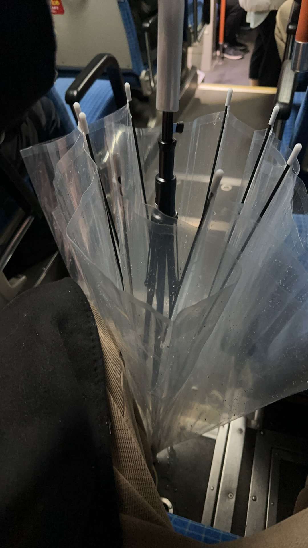
Unfortunately, it started to rain heavily when we arrived at the station. So I got an important piece of equipment, a transparent umbrella, at a convenience store. By the way, when Japanese buses stop, the passenger side will be lowered, which is pretty good.
This time we raided Fushimi Inari Taisha Shrine at night. Although it was a bit like the underworld, the atmosphere of the attraction did not make people feel scary.


Scenes that can only appear in anime come one after another, and it feels really magical.


It's especially like the empty shots of the male and female protagonists after get off work in Japanese dramas.

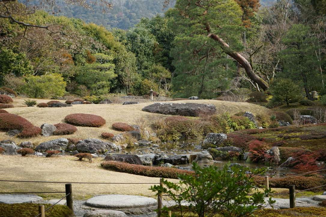
If I had to rank the attractions, I would not hesitateNo neighborsThe courtyard has a view of Higashiyama and is located in the Nanzenji area.

The official website for booking tickets is below. Currently only VISA, MasterCard and JCB are supported:
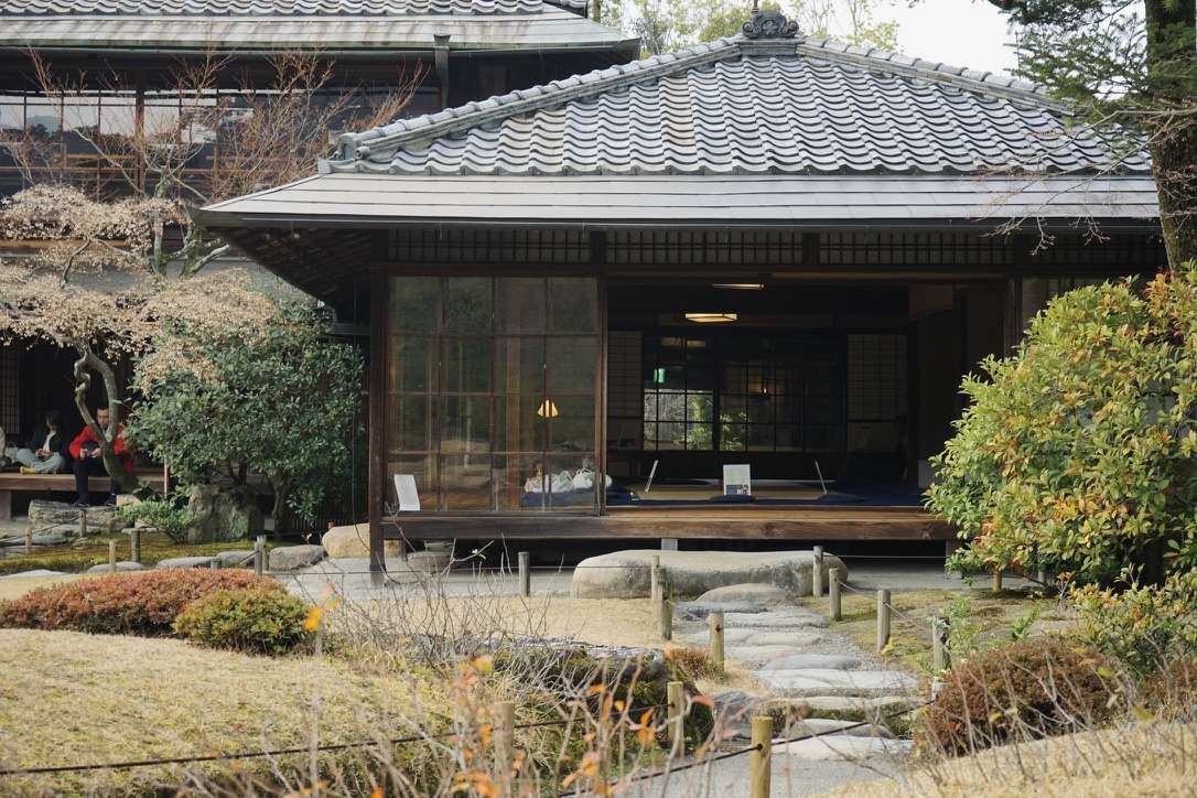
The small but beautiful Japanese garden is actually a Western-style building from the Meiji period. The main house is a simple wooden corrugated tile building. In order to allow guests to fully appreciate the garden, the building's shape is simple and generous.
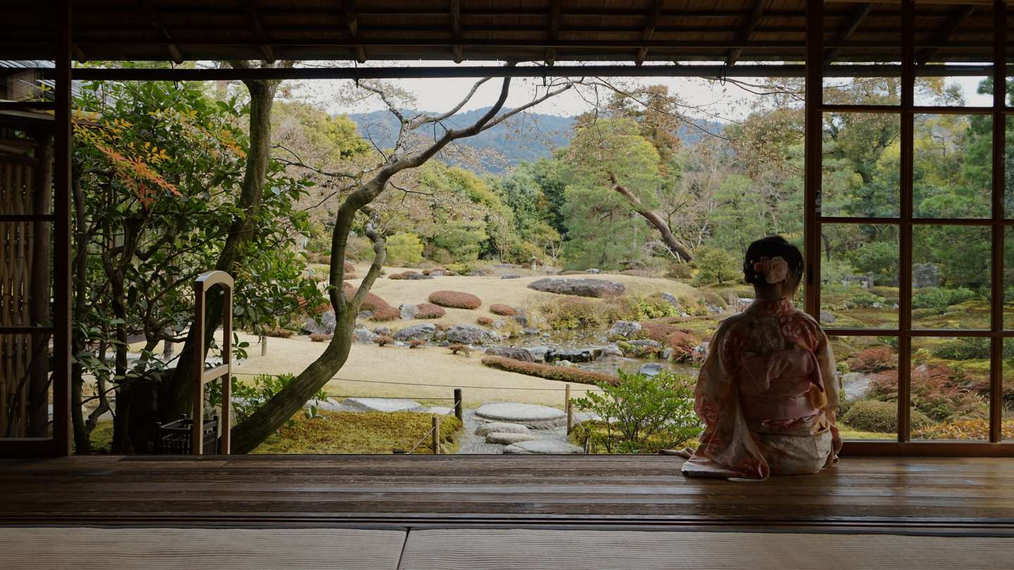
Please note that portrait photography requires additional payment.Or a battle of wits and courage with managers.
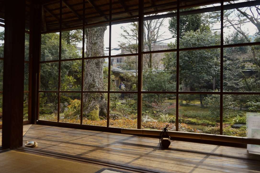
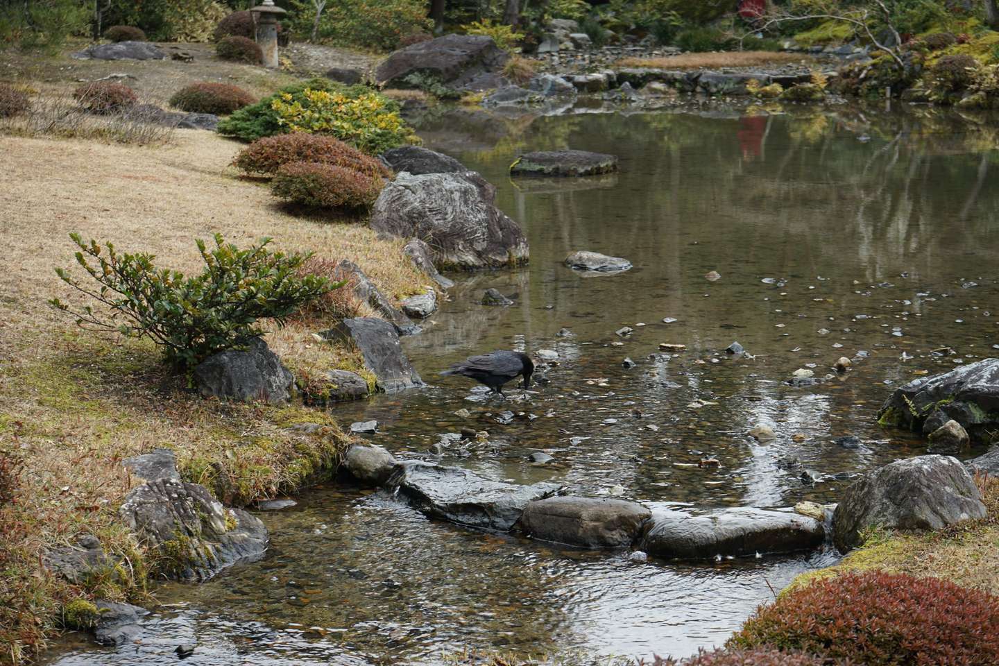
The garden features a bright and open lawn space and a gently flowing stream that draws water from the Lake Biwa Canal.
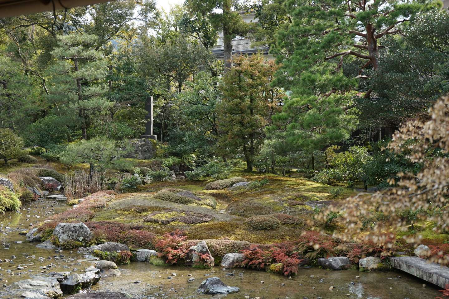
The flowing water design of the courtyard is also inherited from the designer Shanxian Youpeng's preference.
After leaving the courtyard, there is a restaurant run by an old lady at the door. The grandmother and grandson at the next table heard the background music of "The Sound of Music" playing in the restaurant, and they danced and sang along, which was particularly healing.

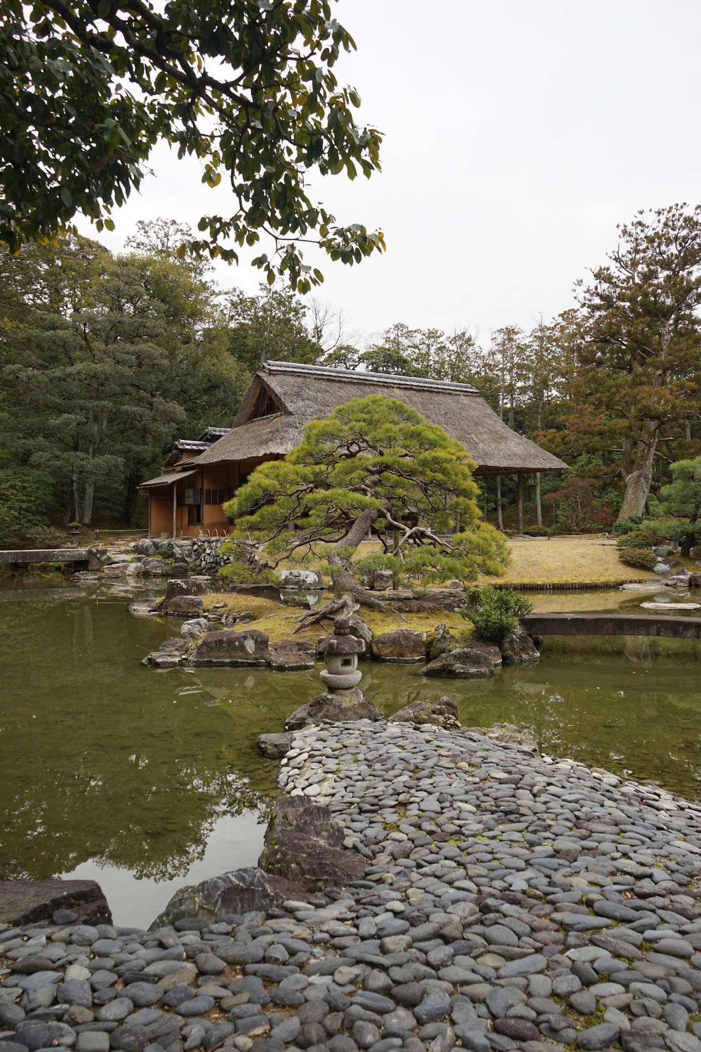
Katsura Imperial Villa is located in a rather awkward position in the southwest of Kyoto. One of the characteristics of this area is that it is less visited by tourists and is quiet.

This attraction was recommended to us by a professor of architecture. Friends who like landscapes should not miss it.
Although I am not a landscape professional, I can personally feel what "Artificiality in natureWhat is "One step, one view”.
And the key point is that you never see the whole courtyard, which is a very unique experience.

Some people say this is the most beautiful garden in Japan, and I don't deny it.
There were only Japanese-speaking guides in the garden, but almost all the tourists were not Japanese, and everyone wore translators, which was quite funny.

There is a peaceful atmosphere both inside and outside the courtyard.

The courtyard is designed in a linear way. Every step you take will give you a completely different view, just like a game level design.
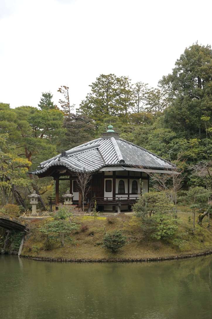
There are many bridges, and the guide specifically reminded us not to take photos on the bridges.

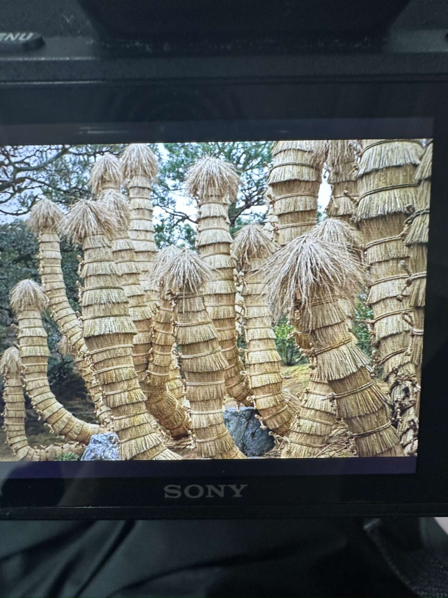
Does anyone know what this is?
One of the most anticipated attractions in this Kyoto trip, Ryoan-ji Temple, is next to Kinkaku-ji Temple. These two attractions are close to each other, and you can choose to take the bus to commute, or you can walk like I did.

The Japanese dry landscape really gives me a sense of desolation and mystery. The most famous of these is the dry landscape of Ryoanji Temple.
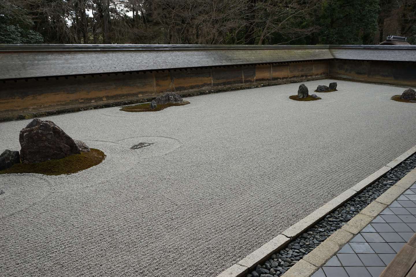
To be honest, after visiting Ryoanji Temple, I was quite disappointed.
That said, the dry landscape garden at Ryoan-ji Temple is very small, and the photo above is almost 90%.
After walking out of Ryoanji Temple in disappointment, I met an old American couple with an English-speaking guide. My friend and I shamelessly followed them and saw the scenery below.


I'm sure you've all experienced the beauty of Kinkaku-ji Temple in Mishima's writings. But when I saw the golden glow with my own eyes, I couldn't help but be shocked.

I bought a few amulets for good luck next to Kinkakuji Temple.


This is a tourist spot that most people will visit when they come to Kyoto. You can walk along Ninenzaka/Sannenzaka.
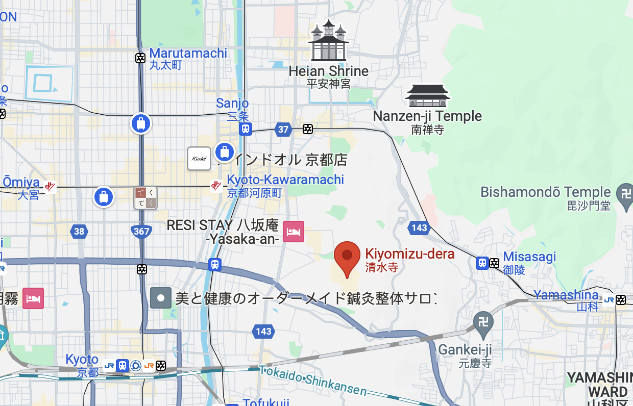
There are really a lot of people here.


A friend said that this photo of mine was over-edited and looked too much like an anime. Actually, this is the original photo.

As the sky gradually darkened, I saw an anime-like scene and felt inexplicably moved.


I have to say that Kyoto is really suitable for hiking and is indeed a pedestrian-friendly city.


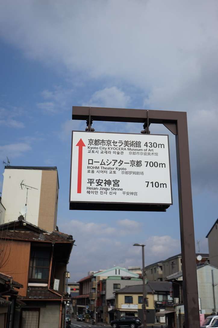


You have to eat some wheat when you come to Kyoto.

This is the Hong BBQ restaurant that turned us away on the first night. The prices at this restaurant are still quite high.


This is a small restaurant that my friend and I found on the way to Nanzenji Temple.

I experienced the three-course meal.

The price is also quite touching.

The most distinctive one is the mackerel. It is cold and tastes like canned mackerel, with a lighter flavor.

It may be difficult to have such an opportunity again to go to the place I want to go with my friends.
Life is short, so cherish every moment you have.

Project (BIRP) on Github:
https://github.com/Remyuu/Unity-Interactive-Grass

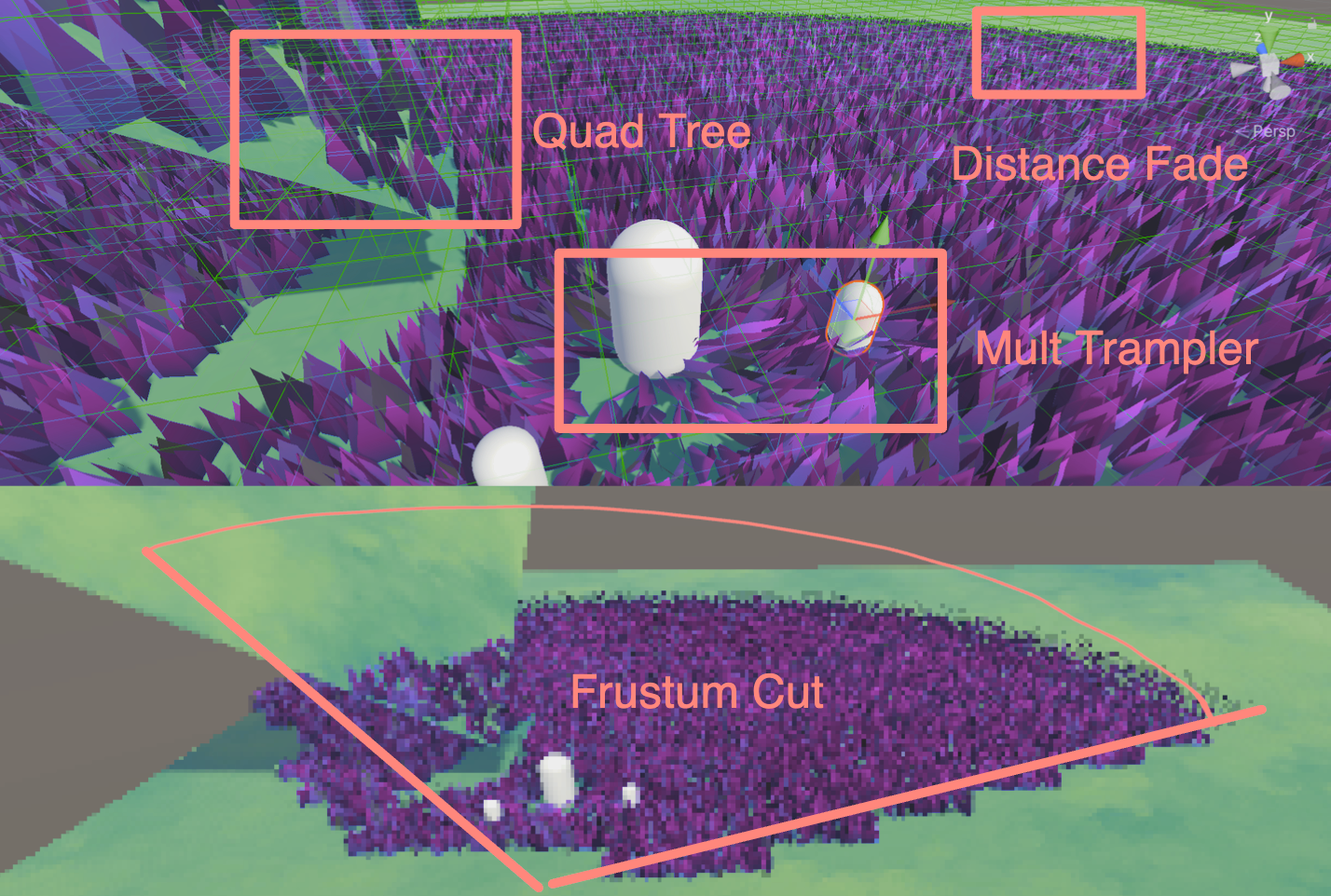

First, here is a screenshot of 10,0500 grasses running on Compute Shader on my M1 pro without any optimization. It can run more than 200 frames.

After adding octree frustum culling, distance fading and other operations, the frame rate is not so stable (I want to die). I guess it is because the CPU has too much pressure to operate each frame and needs to maintain such a large amount of grass information. But as long as enough culling is done, running 700+ frames is no problem (comfort). In addition, the depth of the octree also needs to be optimized according to the actual situation. In the figure below, I set the depth of the octree to 5.

This article is getting longer and longer. I mainly use it to review my knowledge. When you read it, you may feel that there are a lot of basic contents. I am a complete novice, and I beg for discussion and correction from you.

This article mainly has two stages:
The rendering method of geometry shader + tessellation shader should be relatively simple, but the performance ceiling is relatively low and the platform compatibility is poor.
The method of combining compute shaders with GPU Instancing should be the mainstream method in the current industry, and it can also run well on mobile terminals.

The CS rendering of the sea of grass in this article mainly refers to the implementation of Colin and Minions Art, which is more like a hybrid of the two (the former has been analyzed by a big guy on ZhihuGrass rendering study notes based on GPU Instance). Use three sets of ComputeBuffer, one is the buffer containing all the grass, one is the buffer that is appended into the Material, and the other is a visible buffer (obtained in real time based on frustum culling). Implemented the use of a quad-octree (odd-even depth) for space division, plus the frustum culling to get the index of all the grass in the current frustum, pass it to the Compute Shader for further processing (such as Mesh generation, quaternion calculation rotation, LoD, etc.), and then use a variable-length ComputeBuffer (ComputeBufferType.Append) to pass the grass to be rendered to the Material through Instancing for final rendering.
You can also use the Hi-Z solution to eliminate it. I'm digging a hole and working hard to learn.
In addition, I referred to the article by Minions Art and copied a set of editor grass brushing tools (incomplete version), which stores the positions of all grass vertices by maintaining a vertex list.
Furthermore, by maintaining another set of Cut Buffer, if the grass is marked with a -1 value, it will not be processed. If it is marked with a non--1 value of the chopper height, it will be passed to the Material, and through the WorldPos + Split.y plus the lerp operation, the upper half of the grass will be made invisible, and the color of the grass will be modified, and finally some grass clippings will be added to achieve a grass-cutting effect.

Previous articleI have introduced in detail what a tessellation shader is and various optimization methods. Next, I will integrate tessellation into actual development. In addition, I combined the compute shader I learned in a few days to create a grass field based on the compute shader. You can find more details in the following article.This noteThe following is the small effect that this article will achieve, with complete code attached:
Main references(plagiarism)article:
There are many ways to render grass, two of which are shown in this article:
First of all, the first solution has great limitations. Many mobile devices and Metal do not support GS, and GS will recalculate the Mesh every frame, which is quite expensive.
Secondly, can MacOS no longer run geometry shaders? Not really. If you want to use GS, you must use OpenGL, not Metal. But it should be noted that Apple supports OpenGL up to OpenGL 4.1. In other words, this version does not support Compute Shader. Of course, MacOS in the Intel era can support OpenGL 4.3 and can run CS and GS at the same time. The M series chips do not have this fate. Either use 4.1 or use Metal. On my M1p mbp, even if you choose a virtual machine (Parallels 18+ provides DX11 and Vulkan), the Vulkan running on macOS is translated and is essentially Metal, so there is still no GS. Therefore, there is no native GS after macOS M1.
Furthermore, Metal doesn't even support Tessellation shaders directly. Apple doesn't want to support these two things on the chip at all. Why? Because the efficiency is too low. On the M chip, TS is even simulated by CS!
To sum up, geometry shaders are a dead-end technology, especially after the advent of Mesh Shader. Although GS is very popular in Unity, any similar effect can be instanced on CS, and it is more efficient. Although new graphics cards will still support GS, there are still quite a few games on the market that use GS. It's just that Apple didn't consider compatibility and directly cut it off.

This article explains in detail why GS is so slow:http://www.joshbarczak.com/blog/?p=667. Simply put, Intel optimized GS by blocking threads, etc., while other chips do not have this optimization.
This article is a study note and is likely to contain errors.
This chapter isRoystanA concise summary of the . If you need the project file or the final code, you can download it from the original article. Or readSocrates has no bottom article.
After the Domain Stage, you can choose to use a geometry shader.

A geometry shader takes a whole primitive as input and is able to generate vertices on output. The input to a geometry shader is the vertices of a complete primitive (three vertices for a triangle, two vertices for a line or a single vertex for a point). The geometry shader is called once for each primitive.
fromWeb DownloadInitial engineering.
Draw a triangle.
// Add inside the CGINCLUDE block.
struct geometryOutput
{
    float4 pos : SV_POSITION;
};

...
    //Vertex shader
return vertex;
...

[maxvertexcount(3)]
void geo(triangle float4 IN[3] : SV_POSITION, inout TriangleStreamtriStream)
{
    geometryOutput o;

    o.POS = UnityObjectToClipPos(float4(0.5, 0, 0, 1));
    triStream.Append(o);

    o.POS = UnityObjectToClipPos(float4(-0.5, 0, 0, 1));
    triStream.Append(o);

    o.POS = UnityObjectToClipPos(float4(0, 1, 0, 1));
    triStream.Append(o);
}

…

// Add inside the SubShader Pass, just below the #pragma fragment frag line.
#pragma geometry geo
We actually draw a triangle for each vertex in the mesh, but the positions we assign to the triangle vertices are constant - they don't change for each input vertex - placing all the triangles on top of each other.
Therefore, we can just make an offset according to the position of each vertex.
// Add to the top of the geometry shader.
float3 POS = IN[0];

…

// Update each assignment of o.pos.
o.POS = UnityObjectToClipPos(POS + float3(0.5, 0, 0));

…

o.POS = UnityObjectToClipPos(POS + float3(-0.5, 0, 0));

…

o.POS = UnityObjectToClipPos(POS + float3(0, 1, 0));However, it should be noted that currently all triangles are emitted in one direction, so normal correction is added. TBN matrix is constructed and multiplied with the current direction. And the code is organized.
float3 vNormal = IN[0].normal;
float4 vTangent = IN[0].tangent;
float3 vBinormal = cross(vNormal, vTangent) * vTangent.w;

float3x3 tangentToLocal = float3x3(
    vTangent.x, vBinormal.x, vNormal.x,
    vTangent.y, vBinormal.y, vNormal.y,
    vTangent.z, vBinormal.z, vNormal.z
    );

triStream.Append(VertexOutput(POS + mul(tangentToLocal, float3(0.5, 0, 0))));
triStream.Append(VertexOutput(POS + mul(tangentToLocal, float3(-0.5, 0, 0))));
triStream.Append(VertexOutput(POS + mul(tangentToLocal, float3(0, 0, 1))));
Then define the upper and lower colors of the grass, and use UV to make a lerp gradient.
return lerp(_BottomColor, _TopColor, i.uv.y);
Make a random orientation. Here a rotation matrix is constructed. The principle is also mentioned in GAMES101. There is also aVideo of formula derivation, and it is very clear! The simple derivation idea is, assuming that the vector $a$ rotates around the n-axis to $b$, then decompose $a$ into the component parallel to the n-axis (found to be constant) plus the component perpendicular to the n-axis.

float3x3 AngleAxis3x3(float angle, float3 axis)
{
    float c, s;
    sincos(angle, s, c);

    float t = 1 - c;
    float x = axis.x;
    float y = axis.y;
    float z = axis.z;

    return float3x3(
        t * x * x + c, t * x * y - s * z, t * x * z + s * y,
        t * x * y + s * z, t * y * y + c, t * y * z - s * x,
        t * x * z - s * y, t * y * z + s * x, t * z * z + c
        );
}
The rotation matrix $R$ is calculated here using Rodrigues' rotation formula: $$R=I+sin(θ)⋅[k]×+(1−cos(θ))⋅[k]×2$$
Among them, $\theta$ is the rotation angle. $k$ is the unit rotation axis. $I$ is the identity matrix. $[k]_{\times}$ is the antisymmetric matrix corresponding to the axis $k$.
For a unit vector $k=(x,y,z)$ , the antisymmetric matrix $[k]_{\times}=\left[\begin{array}{ccc} 0 & -z & y \\ z & 0 & -x \\ -y & x & 0 \end{array}\right]$ finally obtains the matrix elements:
$$ \begin{array}{ccc} tx^2 + c & txy – sz & txz + sy \\ txy + sz & ty^2 + c & tyz – sx \\ txz – sy & tyz + sx & tz^2 + c \\ \end{array} $$
float3x3 facingRotationMatrix = AngleAxis3x3(rand(POS) * UNITY_TWO_PI, float3(0, 0, 1));
Get the grass in a random direction, and then pour it in any random direction on the x or y axis.
float3x3 bendRotationMatrix = AngleAxis3x3(rand(POS.zzx) * _BendRotationRandom * UNITY_PI * 0.5, float3(-1, 0, 0));
Adjust the width and height of the grass. Originally, we set the height and width to be one unit. To make the grass more natural, we add rand to this step to make it look more natural.
_BladeWidth("Blade Width", Float) = 0.05
_BladeWidthRandom("Blade Width Random", Float) = 0.02
_BladeHeight("Blade Height", Float) = 0.5
_BladeHeightRandom("Blade Height Random", Float) = 0.3


float height = (rand(POS.zyx) * 2 - 1) * _BladeHeightRandom + _BladeHeight;
float width = (rand(POS.xzy) * 2 - 1) * _BladeWidthRandom + _BladeWidth;


triStream.Append(VertexOutput(POS + mul(transformationMatrix, float3(width, 0, 0)), float2(0, 0)));
triStream.Append(VertexOutput(POS + mul(transformationMatrix, float3(-width, 0, 0)), float2(1, 0)));
triStream.Append(VertexOutput(POS + mul(transformationMatrix, float3(0, 0, height)), float2(0.5, 1)));
Since the number is too small, the upper surface is subdivided here.

To animate the grass, add the normals to the _Time perturbation. Sample the texture, then calculate the wind rotation matrix and apply it to the grass.
float2 uv = POS.xz * _WindDistortionMap_ST.xy + _WindDistortionMap_ST.z + _WindFrequency * _Time.y;

float2 windSample = (tex2Dlod(_WindDistortionMap, float4(uv, 0, 0)).xy * 2 - 1) * _WindStrength;

float3 wind = normalize(float3(windSample.x, windSample.y, 0));

float3x3 windRotation = AngleAxis3x3(UNITY_PI * windSample, wind);

float3x3 transformationMatrix = mul(mul(mul(tangentToLocal, windRotation), facingRotationMatrix), bendRotationMatrix);At this time, the wind may rotate along the x and y axes, which is specifically manifested as:

Write a matrix for the two points under your feet that rotates only along z.
float3x3 transformationMatrixFacing = mul(tangentToLocal, facingRotationMatrix);

…

triStream.Append(VertexOutput(POS + mul(transformationMatrixFacing, float3(width, 0, 0)), float2(0, 0)));
triStream.Append(VertexOutput(POS + mul(transformationMatrixFacing, float3(-width, 0, 0)), float2(1, 0)));In order to make the leaves have curvature, we have to add vertices. In addition, since double-sided rendering is currently enabled, the order of vertices does not matter. Here, a manual interpolation for loop is used to construct triangles. A forward is calculated to bend the leaves.
float forward = rand(POS.yyz) * _BladeForward;


for (int i = 0; i < BLADE_SEGMENTS; i++)
{
    float t = i / (float)BLADE_SEGMENTS;
    // Add below the line declaring float t.
    float segmentHeight = height * t;
    float segmentWidth = width * (1 - t);
    float segmentForward = pow(t, _BladeCurve) * forward;
    float3x3 transformMatrix = i == 0 ? transformationMatrixFacing : transformationMatrix;
    triStream.Append(GenerateGrassVertex(POS, segmentWidth, segmentHeight, segmentForward, float2(0, t), transformMatrix));
    triStream.Append(GenerateGrassVertex(POS, -segmentWidth, segmentHeight, segmentForward, float2(1, t), transformMatrix));
}

triStream.Append(GenerateGrassVertex(POS, 0, height, forward, float2(0.5, 1), transformationMatrix));

Create shadows in another Pass and output.
Pass{
    Tags{
        "LightMode" = "ShadowCaster"
    }

    CGPROGRAM
    #Pragmas vertex vert
    #Pragmas geometry geo
    #Pragmas fragment frag
    #Pragmas hull hull
    #Pragmas domain domain
    #Pragmas target 4.6
    #Pragmas multi_compile_shadowcaster

    float4 frag(geometryOutput i) : SV_Target{
        SHADOW_CASTER_FRAGMENT(i)
    }

    ENDCG
}
Use SHADOW_ATTENUATION directly in Frag to determine the shadow.
// geometryOutput struct.
unityShadowCoord4 _ShadowCoord : TEXCOORD1;
...
o._ShadowCoord = ComputeScreenPos(o.POS);
...
#Pragmas multi_compile_fwdbase
...
return SHADOW_ATTENUATION(i);

Removes surface acne.
#if UNITY_PASS_SHADOWCASTER
    o.POS = UnityApplyLinearShadowBias(o.POS);
#endif
Add normal information to vertices generated by the geometry shader.
struct geometryOutput
{
    float4 POS : SV_POSITION;
    float2 uv : TEXCOORD0;
    unityShadowCoord4 _ShadowCoord : TEXCOORD1;
    float3 normal : NORMAL;
};
...
o.normal = UnityObjectToWorldNormal(normal);

The final effect.

Code:
Complete: https://pastebin.com/U14m1Nu0
I have already written the BIRP version, and now I just need to port it.
You can followThis article by DanielYou can also follow me to modify the code. It should be noted that the space transformation code in the original repo has problems.Pull requestsThe solution was found in
Now put the above BIRP tessellation shader together.
Declare the URP pipeline.
LOD 100
Cull Off
Pass{
    Tags{
        "RenderType" = "Opaque"
        "Queue" = "Geometry"
        "RenderPipeline" = "UniversalPipeline"
    }
Import the URP library.
#include "Packages/com.unity.render-pipelines.universal/ShaderLibrary/Core.hlsl"
#include "Packages/com.unity.render-pipelines.universal/ShaderLibrary/Lighting.hlsl"
#include "Packages/com.unity.render-pipelines.universal/ShaderLibrary/ShaderVariablesFunctions.hlsl"

o._ShadowCoord = ComputeScreenPos(o.POS);
Change the function.
// o.normal = UnityObjectToWorldNormal(normal);
o.normal = TransformObjectToWorldNormal(normal);
URP receives the shadow. It is best to calculate this in the vertex shader, but for convenience, it is all calculated in the geometry shader.

Then generate the shadows. ShadowCaster Pass.
Pass{
    Name "ShadowCaster"
    Tags{ "LightMode" = "ShadowCaster" }

    ZWrite On
    ZTest LEqual

    HLSLPROGRAM

        half4 frag(geometryOutput input) : SV_TARGET{
            return 1;
        }

    ENDHLSL
}
Above we just use a fixed number of subdivision levels, which I cannot accept. If you don't understand the principle of surface subdivision, you can seeMy Tessellation Articles, which details several solutions for optimizing segmentation.
I use the BIRP version of the code that I completed in Section 1 as an example. The current version only has the Uniform subdivision.

_TessellationUniform("Tessellation Uniform", Range(1, 64)) = 1
The output structures of each stage are quite confusing, so let's reorganize them.


[KeywordEnum(INTEGER, FRAC_EVEN, FRAC_ODD, POW2)] _PARTITIONING("Partition algorithm", Float) = 0

#Pragmas shader_feature_local _PARTITIONING_INTEGER _PARTITIONING_FRAC_EVEN _PARTITIONING_FRAC_ODD _PARTITIONING_POW2

#if defined(_PARTITIONING_INTEGER)
    [partitioning("integer")]
#elif defined(_PARTITIONING_FRAC_EVEN)
    [partitioning("fractional_even")]
#elif defined(_PARTITIONING_FRAC_ODD)
    [partitioning("fractional_odd")]
#elif defined(_PARTITIONING_POW2)
    [partitioning("pow2")]
#else
    [partitioning("integer")]
#endifIn BIRP, use _ProjectionParams.z to represent the far plane, and in URP use UNITY_RAW_FAR_CLIP_VALUE.
bool IsOutOfBounds(float3 p, float3 lower, float3 higher) { //Given rectangle judgment
    return p.x < lower.x || p.x > higher.x || p.y < lower.y || p.y > higher.y || p.z < lower.z || p.z > higher.z;
}
bool IsPointOutOfFrustum(float4 positionCS) { //View cone judgment
    float3 culling = positionCS.xyz;
    float w = positionCS.w;
    float3 lowerBounds = float3(-w, -w, -w * _ProjectionParams.z);
    float3 higherBounds = float3(w, w, w);
    return IsOutOfBounds(culling, lowerBounds, higherBounds);
}
bool ShouldClipPatch(float4 p0PositionCS, float4 p1PositionCS, float4 p2PositionCS) {
    bool allOutside = IsPointOutOfFrustum(p0PositionCS) &&
        IsPointOutOfFrustum(p1PositionCS) &&
        IsPointOutOfFrustum(p2PositionCS);
    return allOutside;
}

TessellationControlPoint vert(Attributes v)
{
    ...
    o.positionCS = UnityObjectToClipPos(v.vertex);
    ...
}

TessellationFactors patchConstantFunction (InputPatch<TessellationControlPoint, 3> patch)
{
    TessellationFactors f;
    if(ShouldClipPatch(patch[0].positionCS, patch[1].positionCS, patch[2].positionCS)){
        f.edge[0] = f.edge[1] = f.edge[2] = f.inside = 0;
    }else{
        f.edge[0] = _TessellationFactor;
        f.edge[1] = _TessellationFactor;
        f.edge[2] = _TessellationFactor;
        f.inside = _TessellationFactor;
    }
    return f;
}
However, it should be noted that the judgment input here is the CS coordinates of the grass. If the triangular grass completely leaves the screen, but the grass grows high and may still be on the screen, it will cause a screen bug where the grass suddenly disappears. This depends on the needs of the project. If it is a project with an upward viewing angle and the grass is relatively short, this operation can be used.
The viewing angle is not a big problem.

If viewed from Voldemort's perspective, the grass is incomplete and over-culled.

The grass is dense near and sparse far, but based on the screen distance (CS space). This method is affected by the resolution.
float EdgeTessellationFactor(float scale, float4 p0PositionCS, float4 p1PositionCS) {
    float factor = distance(p0PositionCS.xyz / p0PositionCS.w, p1PositionCS.xyz / p1PositionCS.w) / scale;
    return max(1, factor);
}

TessellationFactors patchConstantFunction (InputPatch<TessellationControlPoint, 3> patch)
{
    TessellationFactors f;

    f.edge[0] = EdgeTessellationFactor(_TessellationFactor,
        patch[1].positionCS, patch[2].positionCS);
    f.edge[1] = EdgeTessellationFactor(_TessellationFactor,
        patch[2].positionCS, patch[0].positionCS);
    f.edge[2] = EdgeTessellationFactor(_TessellationFactor,
        patch[0].positionCS, patch[1].positionCS);
    f.inside = (f.edge[0] + f.edge[1] + f.edge[2]) / 3.0;


    #if defined(_CUTTESS_TRUE)
        if(ShouldClipPatch(patch[0].positionCS, patch[1].positionCS, patch[2].positionCS))
            f.edge[0] = f.edge[1] = f.edge[2] = f.inside = 0;
    #endif

    return f;
}
Tessellation Factor = 0.08


It is not recommended to select Frac as the segmentation mode, otherwise there will be strong shaking, which is very eye-catching. I don't like this method very much.
Calculate the ratio of "the distance between two points" to "the distance between the midpoint of the two vertices and the camera position". The larger the ratio, the larger the space occupied on the screen, and the more subdivision is required.
float EdgeTessellationFactor_WorldBase(float scale, float3 p0PositionWS, float3 p1PositionWS) {
    float length = distance(p0PositionWS, p1PositionWS);
    float distanceToCamera = distance(_WorldSpaceCameraPos, (p0PositionWS + p1PositionWS) * 0.5);
    float factor = length / (scale * distanceToCamera * distanceToCamera);
    return max(1, factor);
}
...
f.edge[0] = EdgeTessellationFactor_WorldBase(_TessellationFactor_WORLD_BASE,
    patch[1].vertex, patch[2].vertex);
f.edge[1] = EdgeTessellationFactor_WorldBase(_TessellationFactor_WORLD_BASE,
    patch[2].vertex, patch[0].vertex);
f.edge[2] = EdgeTessellationFactor_WorldBase(_TessellationFactor_WORLD_BASE,
    patch[0].vertex, patch[1].vertex);
f.inside = (f.edge[0] + f.edge[1] + f.edge[2]) / 3.0;

There is still room for improvement. Adjust the density of the grass so that the grass at close distance is not too dense, and the grass curve at medium distance is smoother, and introduce a nonlinear factor to control the relationship between distance and tessellation factor.
float EdgeTessellationFactor_WorldBase(float scale, float3 p0PositionWS, float3 p1PositionWS) {
    float length = distance(p0PositionWS, p1PositionWS);
    float distanceToCamera = distance(_WorldSpaceCameraPos, (p0PositionWS + p1PositionWS) * 0.5);
    // Use the square root function to adjust the effect of distance to make the tessellation factor change more smoothly at medium distances
    float adjustedDistance = sqrt(distanceToCamera);
    // Adjust the impact of scale. You may need to further fine-tune the coefficient here based on the actual effect.
    float factor = length / (scale * adjustedDistance);
    return max(1, factor);
}
This is more appropriate.


The vertex shader reads the texture and passes it to the tessellation shader, which calculates the tessellation logic in PCF.
Take FIXED mode as an example:
_VisibilityMap("Visibility Map", 2D) = "white" {}
TEXTURE2D (_VisibilityMap);SAMPLER(sampler_VisibilityMap);
struct Attributes
{
    ...
    float2 uv : TEXCOORD0;
};
struct TessellationControlPoint
{
    ...
    float visibility : TEXCOORD1;
};
TessellationControlPoint vert(Attributes v){
    ...
    float visibility = SAMPLE_TEXTURE2D_LOD(_VisibilityMap, sampler_VisibilityMap, v.uv, 0).r;
    o.visibility    = visibility;
    ...
}
TessellationFactors patchConstantFunction (InputPatch<TessellationControlPoint, 3> patch){
    ...
    float averageVisibility = (patch[0].visibility + patch[1].visibility + patch[2].visibility) / 3; // Calculate the average grayscale value of the three vertices
    float baseTessellationFactor = _TessellationFactor_FIXED;
    float tessellationMultiplier = lerp(0.1, 1.0, averageVisibility); // Adjust the factor based on the average gray value
    #if defined(_DYNAMIC_FIXED)
        f.edge[0] = _TessellationFactor_FIXED * tessellationMultiplier;
        f.edge[1] = _TessellationFactor_FIXED * tessellationMultiplier;
        f.edge[2] = _TessellationFactor_FIXED * tessellationMultiplier;
        f.inside  = _TessellationFactor_FIXED * tessellationMultiplier;
...Grass Shader:

There are some differences in URP. For example, to calculate ShadowBias, you need to do the following. I won’t expand on it. Just look at the code yourself.
#if UNITY_PASS_SHADOWCASTER
    // o.pos = UnityApplyLinearShadowBias(o.pos);
    o.shadowCoord = TransformWorldToShadowCoord(ApplyShadowBias(posWS, norWS, 0));
#endif
Grass Shader:
URP and BIRP are exactly the same.
The principle is very simple. The script transmits the character's world coordinates, and then bends the grass according to the set radius and interaction strength.
uniform float3 _PositionMoving; // Object position float _Radius; // Object interaction radius float _Strength; // Interaction strength
In the grass generation loop, calculate the distance between each grass fragment and the object and adjust the grass position according to this distance.
float dis = distance(_PositionMoving, posWS); // Calculate distance
float radiusEffect = 1 - saturate(dis / _Radius); // Calculate effect attenuation based on distance
float3 sphereDisp = POS - _PositionMoving; // Calculate the position difference
sphereDisp *= radiusEffect * _Strength; // Apply falloff and intensity
sphereDisp = clamp(sphereDisp, -0.8, 0.8); // Limit the maximum displacement
The new positions are then calculated within each blade of grass.
// Apply interactive effects
float3 newPos = i == 0 ? POS : POS + (sphereDisp * t);
triStream.Append(GenerateGrassVertex(newPos, segmentWidth, segmentHeight, segmentForward, float2(0, t), transformMatrix));
triStream.Append(GenerateGrassVertex(newPos, -segmentWidth, segmentHeight, segmentForward, float2(1, t), transformMatrix));
Don't forget the outside of the for loop, which is the top vertex.
// Final grass fragment
float3 newPosTop = POS + sphereDisp;
triStream.Append(GenerateGrassVertex(newPosTop, 0, height, forward, float2(0.5, 1), transformationMatrix));
triStream.RestartStrip();
In URP, using uniform float3 _PositionMoving may cause SRP Batcher to fail.


Bind the object that needs interaction.
using UnityEngine;

public class ShaderInteractor : MonoBehaviour
{
    // Update is called once per frame
    void Update()
    {
        Shader.SetGlobalVector("_PositionMoving", transform.position);
    }
}Grass shader:
Why v1.0? Because I think it is quite difficult to render the sea of grass with this compute shader. Many of the things that are not available now can be improved slowly in the future. I also wrote some notes about Compute Shader.
The Compute Shader notes above fully describe how to write a stylized grass sea from scratch in CS. If you forgot, review it here.

There are still many things that the CPU needs to do in the initialization stage. First, define the grass Mesh and Buffer transfer (the width and height of the grass, the position of each grass generation, the random orientation of the grass, and the random color depth of the grass). It also needs to specifically pass the maximum curvature value and grass interaction radius to the Compute Shader.
For each frame, the CPU also passes the time variable, wind direction, wind force/speed, and wind field scaling factor to the Compute Shader.
Compute Shader uses the information passed by the CPU to calculate how the grass should turn, using quaternions as output.
Finally, the shader instantiates the ID and all calculation results, first calculating the vertex offset, then applying the quaternion rotation, and finally modifying the normal information.
This demo can actually be further optimized, such as putting more calculations in the Compute Shader, such as the process of generating Mesh, the width and height of the grass, random tilting, etc. More real-time parameter adjustment variables can also be optimized. Various optimization culling can also be performed, such as culling the incoming camera position by distance, or culling with the view frustum, etc. This culling process requires the use of some atomic operations. There is also multi-object interaction. The logic of interactive grass deformation can also be optimized, such as the degree of interaction is proportional to the power of the distance of the interactive object, etc. The engine function can also be increased, and the function of brushing grass can be developed, which may require a quadtree storage system, etc.
And in Compute Shader, use vectors instead of scalars when possible.
First, organize the code. Put all variables that do not need to be sent to the Compute Shader every frame into a function for unified initialization. Organize the Inspector panel. (There are many code changes)

First, basically all calculations are run on the GPU, except that the world coordinates of each grass are calculated in the CPU and passed to the GPU through a Buffer.

The size of the buffer transmission depends entirely on the size of the ground mesh and the set density. In other words, if it is a super large open world, the buffer will become super large. For a 5*5 grass field, with the Density set to 0.5, approximately 312576 grass data will be sent, and the actual data will reach 4*312576*4=5001216 bytes. Based on the CPU->GPU transmission speed of 8 GB/s, it takes about 10 milliseconds to transmit.

Fortunately, this buffer does not need to be transmitted every frame, but it is enough to attract our attention. If the current grass size increases to 100*100, the time required will increase several times, which is scary. Moreover, we may not use many of the vertices, which causes a great waste of performance.
I added a function to generate perlin noise in the Compute Shader, as well as the xorshift128 random number generation algorithm.
// Perlin random number algorithm
float hash(float x, float y) {
    return frac(abs(sin(sin(123.321 + x) * (y + 321.123)) * 456.654));
}
float perlin(float x, float y){
    float col = 0.0;
    for (int i = 0; i < 8; i++) {
        float fx = floor(x); float fy = floor(y);
        float xx = ceil(x); float cy = ceil(y);
        float a = hash(fx, fy); float b = hash(fx, cy);
        float c = hash(xx, fy); float d = hash(xx, cy);
        col += lerp(lerp(a, b, frac(y)), lerp(c, d, frac(y)), frac(x));
        col /= 2.0; x /= 2.0; y /= 2.0;
    }
    return col;
}
// XorShift128 random number algorithm -- Edited Directly output normalized data
uint state[4];
void xorshift_init(uint s) {
    state[0] = s; state[1] = s | 0xffff0000u;
    state[2] = s < 16; state[3] = s >> 16;
}
float xorshift128() {
    uint t = state[3]; uint s = state[0];
    state[3] = state[2]; state[2] = state[1]; state[1] = s;
    t ^= t < 11u; t ^= t >> 8u;
    state[0] = t ^ s ^ (s >> 19u);
    return (float)state[0] / float(0xffffffffu);
}

[numthreads(THREADGROUPSIZE,1,1)]
void BendGrass (uint3 id : SV_DispatchThreadID)
{
    xorshift_init(id.x * 73856093u ^ id.y * 19349663u ^ id.z * 83492791u);
    ...
}
To review, at present, the CPU uses an AABB average grass paving logic to generate all possible grass vertices, which are then passed to the GPU to perform some culling, LoD and other operations in the Compute Shader.

So far I have three Buffers.

m_InputBuffer is the structure on the left of the above picture that sends all the grass to the GPU without any culling.
m_OutputBuffer is a variable length buffer that increases slowly in the Compute Shader. If the grass of the current thread ID is suitable, it will be added to this buffer for instanced rendering later. The structure on the right of the above picture.
m_argsBuffer is a parameterized Buffer, which is different from other Buffers. It is used to pass parameters to Draw, and its specific content is to specify the number of vertices to be rendered in batches, the number of rendering instances, etc. Let's take a look at it in detail:

First parameter, my grass mesh has seven triangles, so there are 21 vertices to render.
The second parameter is temporarily set to 0, indicating that nothing needs to be rendered. This number will be dynamically set according to the length of m_OutputBuffer after the Compute Shader calculation is completed. In other words, the number here will be the same as the number of grasses appended in the Compute Shader.
The third and fourth parameters represent respectively: the index of the first rendered vertex and the index of the first instantiation.
I haven't used the fifth parameter, so I don't know what it is used for.
The last step looks like this, passing in the Mesh, material, AABB and parameter Buffer.

Create a new C# script and save it in the Editor directory of the project (if it doesn't exist, create one). The script inherits from Editor, and then write [CustomEditor(typeof(XXX))] . It means you work for XXX. I work for GrassControl, and then you can attach what you wrote now to XXX. Of course, you can also have a separate window, which should inherit from EditorWindow.

Write tools in the OnInspectorGUI() function, for example, write a Label.
GUILayout.Label("== Remo Grass Generator ==");
To center the Inspector, add a parameter.
GUILayout.Label("== Remo Grass Generator ==", new GUIStyle(EditorStyles.boldLabel) { alignment = TextAnchor.MiddleCenter });
Too crowded? Just add a line of space.
EditorGUILayout.Space();
If you want to attach tools above XXX, then all the logic should be written above OnInspectorGUI.
... // Write here
// The default Inspector interface of GrassControl
base.OnInspectorGUI();
Create a button and press the code:
if (GUILayout.Button("xxx"))
{
    ...//Code after pressing
Anyway, these are the ones I use now.
It is also very simple to get the Object of the script of the current service and display it in the Inspector.
[SerializeField] private GameObject grassObject;
...
grassObject = (GameObject)EditorGUILayout.ObjectField("Write any name", grassObject, typeof(GameObject), true);
if (grassObject == null)
{
    grassObject = FindObjectOfType<GrassControl>()?.gameObject;
}
After obtaining it, you can access the contents of the current script through GameObject.
How to get the object selected in the Editor window? It can be done with one line of code.
foreach (GameObject obj in Selection.gameObjects)Display the selected objects in the Inspector panel. Note that you need to handle the case of multiple selections, otherwise a Warning will be issued.
// Display the current Editor selected object in real time and control the availability of the button
EditorGUILayout.LabelField("Selection Info:", EditorStyles.boldLabel);
bool hasSelection = Selection.activeGameObject != null;
GUI.enabled = hasSelection;
if (hasSelection)
    foreach (GameObject obj in Selection.gameObjects)
        EditorGUILayout.LabelField(obj.name);
else
    EditorGUILayout.LabelField("No active object selected.");
Next, get the MeshFilter and Renderer of the selected object. Since Raycast detection is required, get a Collider. If it does not exist, create one.

Then I will not talk about the code of sketching grass here.
After generating a bunch of grass, add each grass to the AABB and finally pass it to Instancing.

I assume that each grass is the size of a unit cube, so it is Vector3.one. If the grass is particularly tall, this should need to be modified.
Stuff each blade of grass into the big AABB and pass the new AABB back to the script's m_LocalBounds for Instancing.
Graphics.DrawMeshInstancedIndirect(blade, 0, m_Material, m_LocalBounds, m_argsBuffer);There is a small problem here. Since the current Material is a Surface Shader, the Vertex of the Surface Shader has calculated the center of the AABB by default to do the vertex offset, so the world coordinates passed in before cannot be used directly. You also need to pass the center of the AABB in and subtract it. It's so strange. I wonder if there is any elegant way.

Currently, all generated grass is passed to the Compute Shader on the CPU, and then all grass is added to the AppendBuffer, which means there is no culling logic.

The simplest culling solution is to cull grass based on the distance between the camera and the grass. In the Inspector panel, open a value to represent the culling distance. Calculate the distance between the camera and the current grass instance. If it is greater than the set value, it will not be added to the AppendBuffer.

First, pass the world coordinates of the camera into C#. Here is the semi-pseudo code:
// Get the camera
private Camera m_MainCamera;

m_MainCamera = Camera.main;

if (m_MainCamera != null)
    m_ComputeShader.SetVector(ID_camreaPos, m_MainCamera.transform.position);
In CS, calculate the distance between the grass and the camera:
float distanceFromCamera = distance(input.position, _CameraPositionWS);
The distance function code is as follows:
float distanceFade = 1 - saturate((distanceFromCamera - _MinFadeDist) / (_MaxFadeDist - _MinFadeDist));If the value is less than 0, return directly.
// skip if out of fading range too
if (distanceFade < 0.001f)
{
    return;
}
In the part between culling and not culling, set the grass width + Fade value to achieve a fading effect.
Result.height = (bladeHeight + bladeHeightOffset * (xorshift128()*2-1)) * distanceFade;
Result.width = (bladeWeight + bladeWeightOffset * (xorshift128()*2-1)) * distanceFade;
...
Result.fade = xorshift128() * distanceFade;
In the figure below, both are set to be relatively small for the convenience of demonstration.

I think the actual effect is quite good and smooth. If the width and height of the grass are not modified, the effect will be greatly reduced.
Of course, you can also modify the logic: do not completely remove the grass that exceeds the maximum drawing range, but reduce the number of drawings; or selectively draw the grass in the transition area.
Both logics are acceptable, and if it were me I would choose the latter.
The so-called frustum culling is to reduce the redundant calculations of GPU through various methods at the CPU stage.
So how do I let the Compute Shader know which grass needs to be rendered and which needs to be culled? My approach is to maintain a set of ID Lists. The length is the number of all grasses. If the current grass needs to be culled, otherwise the index value of the grass that needs to be rendered is recorded.
List<uint> grassVisibleIDList = new List<uint>();

// buffer that contains the ids of all visible instances
private ComputeBuffer m_VisibleIDBuffer;

private const int VISIBLE_ID_STRIDE        =  1 * sizeof(uint);

m_VisibleIDBuffer = new ComputeBuffer(grassData.Count, VISIBLE_ID_STRIDE,
    ComputeBufferType.Structured); //uint only, per visible grass
m_ComputeShader.SetBuffer(m_ID_GrassKernel, "_VisibleIDBuffer", m_VisibleIDBuffer);

m_VisibleIDBuffer?.Release();
Since some grass has been removed before being passed to the Compute Shader, the number of Dispatches is no longer the number of all grasses, but the number of the current List.
// m_ComputeShader.Dispatch(m_ID_GrassKernel, m_DispatchSize, 1, 1);

m_DispatchSize = Mathf.CeilToInt(grassVisibleIDList.Count / threadGroupSize);
Generates a fully visible ID sequence.
void GrassFastList(int count)
{
    grassVisibleIDList = Enumerable.Range(0, count).ToArray().ToList();
}
And each frame should be uploaded to GPU. The preparation is complete, and then use Quad tree to operate this array.
You can consider dividing an AABB into multiple sub-AABBs and then use a quadtree to store and manage them.

Currently, all grass is in one AABB. Next, we build an octree and put all the grass in this AABB into branches. This makes it easy to do frustum culling in the early stages of the CPU.

How to store it? If the current grass has a small vertical drop, then a quadtree is enough. If it is an open world with undulating mountains, then use an octree. However, considering that the grass has a relatively high horizontal density, I use a quadtree + octree structure here. The parity of the depth determines whether the current depth is divided into four nodes or eight nodes. If there is no need for strong height division, it is OK to use an octree, but I feel that the efficiency may be a little lower. Here, it is directly evenly distributed. Later optimization can consider the AABB division method based on variable length dynamic changes.
if (depth % 2 == 0)
{
    ...
    m_children.Add(new CullingTreeNode(topLeftSingle, depth - 1));
    m_children.Add(new CullingTreeNode(bottomRightSingle, depth - 1));
    m_children.Add(new CullingTreeNode(topRightSingle, depth - 1));
    m_children.Add(new CullingTreeNode(bottomLeftSingle, depth - 1));
}
else
{
    ...
    m_children.Add(new CullingTreeNode(topLeft, depth - 1));
    m_children.Add(new CullingTreeNode(bottomRight, depth - 1));
    m_children.Add(new CullingTreeNode(topRight, depth - 1));
    m_children.Add(new CullingTreeNode(bottomLeft, depth - 1));

    m_children.Add(new CullingTreeNode(topLeft2, depth - 1));
    m_children.Add(new CullingTreeNode(bottomRight2, depth - 1));
    m_children.Add(new CullingTreeNode(topRight2, depth - 1));
    m_children.Add(new CullingTreeNode(bottomLeft2, depth - 1));
}
The detection of the view frustum and AABB can be done with GeometryUtility.TestPlanesAABB.
public void RetrieveLeaves(Plane[] frustum, List<Bounds> list, List<int> visibleIDList)
{
    if (GeometryUtility.TestPlanesAABB(frustum, m_bounds))
    {
        if (m_children.Count == 0)
        {
            if (grassIDHeld.Count > 0)
            {
                list.Add(m_bounds);
                visibleIDList.AddRange(grassIDHeld);
            }
        }
        else
        {
            foreach (CullingTreeNode child in m_children)
            {
                child.RetrieveLeaves(frustum, list, visibleIDList);
            }
        }
    }
}
This code is the key part, passing in:
By calling the method of this quad/octree, you can get the list of all bounding boxes and grass within the frustum.
Then all the grass indexes can be made into a Buffer and passed to the Compute Shader.
m_VisibleIDBuffer.SetData(grassVisibleIDList);To get a visual AABB, use the OnDrawGizmos() method.

Pass all the AABBs obtained by culling the view frustum into this function. This way you can see the AABBs intuitively.


Also write everything inside the view frustum to the visible grass.

Here I hit a small pit. I completed the octree and successfully divided many sub-AABBs as shown above. But when I moved the camera, the grass flickered wildly. I was a little lazy and didn't want to make GIF videos. Observe the two pictures below. I just moved the view slightly and changed the current Visibility List. The position of the grass jumped a lot, and it looked like the grass flickered continuously.


I can't figure it out, there is no problem with Compute Shader culling.

The number of dispatches is also calculated based on the length of the visibility list, so there must be enough threads to compute the shader.

And there is no problem with DrawMeshInstancedIndirect.

What's the problem?
After a long debugging, I found that the problem lies in the process of taking random numbers by Xorshift of Compute Shader.
Before using _VisibleIDBuffer, one grass corresponds to one thread ID, which is determined from the moment the grass is born. Now that this group of indexes has been added, and the ID of the incoming random value is not changed to a Visible ID, the random numbers will appear very discrete.

That is to say, all previous IDs are replaced with index values taken from _VisibleIDBuffer!

Currently there is only one trampler passed in. If it is not passed in, an error will be reported, which is unbearable.

There are three parameters about interaction:
Now put trampleRadius into pos (Vector4) (or another one, depending on your needs), and pass the position array into it using SetVectorArray. This way each interactive object can have a dedicated interactive radius. For fat interactive objects, make the radius larger, and for skinny ones, make it smaller. That is, remove the following line:
// In SetGrassDataBase, no need to upload every frame
// m_ComputeShader.SetFloat("trampleRadius", trampleRadius);
become:
// In SetGrassDataUpdate, each frame must be uploaded
// Set up multiple interactive objects
if (trampler.Length > 0)
{
    Vector4[] positions = new Vector4[trampler.Length];
    for (int i = 0; i < trampler.Length; i++)
    {
        positions[i] = new Vector4(trampler[i].transform.position.x, trampler[i].transform.position.y, trampler[i].transform.position.z,
            trampleRadius);
    }
    m_ComputeShader.SetVectorArray(ID_tramplePos, positions);
}
Then you have to pass the number of interactive objects so that the Compute Shader knows how many interactive objects need to be processed. This also needs to be updated every frame. I am used to storing an ID index for objects that are updated every frame, which is more efficient.
// Initializing
ID_trampleLength = Shader.PropertyToID("_trampleLength");
// In each frame
m_ComputeShader.SetFloat(ID_trampleLength, trampler.Length);
I repackaged it:


By modifying the corresponding code, you can adjust the radius of each interactive object on the panel. If you want to enrich this adjustment function, you can consider passing a separate Buffer into it.

In the Compute Shader, it is relatively simple to combine multiple rotations.
// Trampler
float4 qt = float4(0, 0, 0, 1); // 1 in quaternion is like this, the imaginary part is 0
for (int trampleIndex = 0; trampleIndex < trampleLength; trampleIndex++)
{
    float trampleRadius = tramplePos[trampleIndex].a;
    float3 relativePosition = input.position - tramplePos[trampleIndex].xyz;
    float dist = length(relativePosition);
    if (dist < trampleRadius) {
        // Use the power to enhance the effect at close range
        float eff = pow((trampleRadius - dist) / trampleRadius, 2) * trampleStrength;
        float3 direction = normalize(relativePosition);
        float3 newTargetDirection = float3(direction.x * eff, 1, direction.z * eff);
        qt = quatMultiply(MapVector(float3(0, 1, 0), newTargetDirection), qt);
    }
}
The camera currently passed to the Compute Shader is the main camera, which is the one in the game window. Now you want to temporarily get the main camera's lens in the editor (Scene window) and restore it after starting the game. You can use the Scene View GUI to draw events.
Here is an example of remodeling my current code:
#if UNITY_EDITOR
    SceneView view;

    void OnDestroy()
    {
        // When the window is destroyed, remove the delegate
        // so that it will no longer do any drawing.
        SceneView.duringSceneGui -= this.OnScene;
    }

    void OnScene(SceneView scene)
    {
        view = scene;
        if (!Application.isPlaying)
        {
            if (view.camera != null)
            {
                m_MainCamera = view.camera;
            }
        }
        else
        {
            m_MainCamera = Camera.main;
        }
    }
    private void OnValidate()
    {
        // Set up components
        if (!Application.isPlaying)
        {
            if (view != null)
            {
                m_MainCamera = view.camera;
            }
        }
        else
        {
            m_MainCamera = Camera.main;
        }
    }
#endif
When initializing the shader, subscribe to the event at the beginning, and then determine whether the current state is game, and then pass a camera. If it is in edit mode, then m_MainCamera is still NULL.
void InitShader()
{
#if UNITY_EDITOR
    SceneView.duringSceneGui += this.OnScene;
    if (!Application.isPlaying)
    {
        if (view != null && view.camera != null)
        {
            m_MainCamera = view.camera;
        }
    }
#endif
    if (Application.isPlaying)
    {
        m_MainCamera = Camera.main;
    }
    ...
In the frame-by-frame Update function, if it is detected that m_MainCamera is NULL, it is determined that the current mode is edit mode:
// Pass in the camera coordinates
        if (m_MainCamera != null)
            m_ComputeShader.SetVector(ID_camreaPos, m_MainCamera.transform.position);
#if UNITY_EDITOR
        else if (view != null && view.camera != null)
        {
            m_ComputeShader.SetVector(ID_camreaPos, view.camera.transform.position);
        }

#endif

Maintain a set of Cut Buffers
// added for cutting
private ComputeBuffer m_CutBuffer;
float[] cutIDs;
Initializing Buffer
private const int CUT_ID_STRIDE            =  1 * sizeof(float);
// added for cutting
m_CutBuffer = new ComputeBuffer(grassData.Count, CUT_ID_STRIDE, ComputeBufferType.Structured);
// added for cutting
m_ComputeShader.SetBuffer(m_ID_GrassKernel, "_CutBuffer", m_CutBuffer);
m_CutBuffer.SetData(cutIDs);
Don't forget to release it when you disable it.
// added for cutting
m_CutBuffer?.Release();
Define a method to pass in the current position and radius to calculate the position of the grass. Set the corresponding cutID to -1.
// newly added for cutting
public void UpdateCutBuffer(Vector3 hitPoint, float radius)
{
    // can't cut grass if there is no grass in the scene
    if (grassData.Count > 0)
    {
        List<int> grasslist = new List<int>();
        // Get the list of IDS that are near the hitpoint within the radius
        cullingTree.ReturnLeafList(hitPoint, grasslist, radius);
        Vector3 brushPosition = this.transform.position;
        // Compute the squared radius to avoid square root calculations
        float squaredRadius = radius * radius;

        for (int i = 0; i < grasslist.Count; i++)
        {
            int currentIndex = grasslist[i];
            Vector3 grassPosition = grassData[currentIndex].position + brushPosition;

            // Calculate the squared distance
            float squaredDistance = (hitPoint - grassPosition).sqrMagnitude;

            // Check if the squared distance is within the squared radius
            // Check if there is grass to cut, or of the grass is uncut(-1)
            if (squaredDistance <= squaredRadius && (cutIDs[currentIndex] > hitPoint.y || cutIDs[currentIndex] == -1))
            {
                // store cutting point
                cutIDs[currentIndex] = hitPoint.y;
            }

        }
    }
    m_CutBuffer.SetData(cutIDs);
}
Then bind a script to the object that needs to be cut:
using System.Collections;
using System.Collections.Generic;
using UnityEngine;


public class Cutgrass : MonoBehaviour
{
    [SerializeField]
    GrassControl grassComputeScript;

    [SerializeField]
    float radius = 1f;

    public bool updateCuts;

    Vector3 cachedPos;
    // Start is called before the first frame update


    // Update is called once per frame
    void Update()
    {
        if (updateCuts && transform.position != cachedPos)
        {
            Debug.Log("Cutting");
            grassComputeScript.UpdateCutBuffer(transform.position, radius);
            cachedPos = transform.position;

        }
    }

    private void OnDrawGizmos()
    {
        Gizmos.color = new Color(1, 0, 0, 0.3f);
        Gizmos.DrawWireSphere(transform.position, radius);
    }
}
In the Compute Shader, just modify the grass height. (Very straightforward...) You can change the effect to whatever you want.
StructuredBuffer<float> _CutBuffer;// added for cutting

    float cut = _CutBuffer[usableID];
    Result.height = (bladeHeight + bladeHeightOffset * (xorshift128()*2-1)) * distanceFade;
    if(cut != -1){
        Result.height *= 0.1f;
    }
Done!

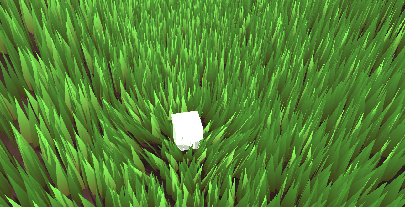
Project address:
https://github.com/Remyuu/Unity-Compute-Shader-Learngithub.com/Remyuu/Unity-Compute-Shader-Learn


The current effect is very ugly, and there are still many details that are not perfect, it is just "implemented". Since I am also a rookie, I hope you can correct me if I write/do it poorly.

Summary of knowledge points:
Preface Reference Articles:

There are many ways to render grass.
The simplest way is to directly paste a grass texture on it.

In addition, eachMesh GrassIt is also common to drag it into the scene. This method has a large operating space and every blade of grass is under control. Although you can use Batching and other methods to optimize and reduce the transmission time from CPU to GPU, this will consume the life of the Ctrl, C, V and D keys on your keyboard. However, you can use L(a, b) in the Transform component to evenly distribute the selected objects between a and b. If you want randomness, you can use R(a, b). For more related operations, seeOfficial Documentation.

Can also be combinedGeometry shaders and tessellation shadersThis method looks good, but one shader can only correspond to one type of geometry (grass). If you want to generate flowers or rocks on this mesh, you need to modify the code in the geometry shader. This problem is not the most critical. The more serious problem is that many mobile devices and Metal do not support geometry shaders at all. Even if they do, they are only software-simulated, with poor performance. And the grass mesh will be recalculated every frame, wasting performance.

BillboardTechnical rendering of grass is also a widely used and long-lasting method. This method works very well when we don't need high-fidelity images. This method is to simply render a Quad+map (Alpha clipping). Use DrawProcedural. However, this method can only be viewed from a distance and not up close, otherwise it will be exposed.

Using UnityTerrain SystemYou can also draw very nice grass. And Unity uses instancing technology to ensure performance. The best part is its brush tool, but if your workflow does not include the terrain system, you can also use third-party plugins to do it.

When searching for information, I also found aImpostors. It's quite interesting to combine the vertex saving advantage of billboards with the ability to realistically reproduce objects from multiple angles. This technology "takes" a Mesh photo of real grass from multiple angles in advance and stores it through Texture. At runtime, the appropriate texture is selected for rendering according to the viewing direction of the current camera. It is equivalent to an upgraded version of the billboard technology. I think the Impostors technology is very suitable for objects that are large but players may need to view from multiple angles, such as trees or complex buildings. However, this method may have problems when the camera is very close or changes between two angles. A more reasonable solution is: use a mesh-based method at very close distances, use Impostors at medium distances, and use billboards at long distances.

The method to be implemented in this article is based on GPU Instancing, which should be called "per-blade mesh grass". This solution is used in games such as "Ghost of Tsushima", "Genshin Impact" and "The Legend of Zelda: Breath of the Wild". Each grass has its own entity, and the light and shadow effects are quite realistic.

Rendering process:

Unity's Instancing technology is quite complex, and I have only seen a glimpse of it. Please correct me if I find any mistakes. The current code is written according to the documentation. GPU instancing currently supports the following platforms:
In addition, Graphics.DrawMeshInstancedIndirect has been eliminated. You should use Graphics.RenderMeshIndirect. This function will automatically calculate the Bounding Box. This is a later story. For details, please see the official documentation:RenderMeshIndirect . This article was also helpful:
https://zhuanlan.zhihu.com/p/403885438.
The principle of GPU Instancing is to send a Draw Call to multiple objects with the same Mesh. The CPU first collects all the information, then puts it into an array and sends it to the GPU at once. The limitation is that the Material and Mesh of these objects must be the same. This is the principle of being able to draw so much grass at a time while maintaining high performance. To achieve GPU Instancing to draw millions of Meshes, you need to follow some rules:
Since Skin Mesh Renderer is not supported,In the previous articleWe bypassed SMR and directly took out the Mesh of different key frames and passed it to the GPU. This is also the reason why the question was raised at the end of the previous article.
There are two main types of Instancing in Unity: GPU Instancing and Procedural Instancing (involving Compute Shaders and Indirect Drawing technology), and the other is the stereo rendering path (UNITY_STEREO_INSTANCING_ENABLED), which I won't go into here. In Shader, the former uses #pragma multi_compile_instancing and the latter uses #pragma instancing_options procedural:setup. For details, please see the official documentationCreating shaders that support GPU instancing .
Then currently the SRP pipeline does not support custom GPU Instancing Shaders, only BIRP can.
Then there is UNITY_PROCEDURAL_INSTANCING_ENABLED . This macro is used to indicate whether Procedural Instancing is enabled. When using Compute Shader or Indirect Drawing API, the attributes of the instance (such as position, color, etc.) can be calculated in real time on the GPU and used directly for rendering without CPU intervention.In the source code, the core code of this macro is:
#ifdef UNITY_PROCEDURAL_INSTANCING_ENABLED #ifndef UNITY_INSTANCING_PROCEDURAL_FUNC #error "UNITY_INSTANCING_PROCEDURAL_FUNC must be defined." #else void UNITY_INSTANCING_PROCEDURAL_FUNC(); // Forward declaration of programmatic function #define DEFAULT_UNITY_SETUP_INSTANCE_ID(input) { UnitySetupInstanceID(UNITY_GET_INSTANCE_ID(input)); UNITY_INSTANCING_PROCEDURAL_FUNC();} #endif #else #define DEFAULT_UNITY_SETUP_INSTANCE_ID(input) { UnitySetupInstanceID(UNITY_GET_INSTANCE_ID(input));} #endifThe Shader is required to define a UNITY_INSTANCING_PROCEDURAL_FUNC function, which is actually the setup() function. If there is no setup() function, an error will be reported.
Generally speaking, what the setup() function needs to do is to extract the corresponding (unity_InstanceID) data from the Buffer, and then calculate the current instance's position, transformation matrix, color, metalness, or custom data and other attributes.
GPU Instancing is just one of Unity's many optimization methods, and you still need to continue learning.
All the CS knowledge points used in this chapter have been covered in the previous article, but the background is changed. Draw a simple diagram.

The implementation is to use GPU Instancing, that is, rendering a large mesh at one time. The core code is just one sentence:
Graphics.DrawMeshInstancedIndirect(mesh, 0, material, bounds, argsBuffer);The Mesh is composed of three Quads and a total of six triangles.

Then add a texture + Alpha Test.

The data structure of grass:
public Vector3 position; // World coordinates, need to be calculated public float lean; public float noise; public GrassClump( Vector3 pos){ position.x = pos.x; position.y = pos.y; position.z = pos.z; lean = 0; noise = Random.Range(0.5f, 1); if (Random.value < 0.5f) noise = -noise; }Pass the buffer of the grass to be rendered (the world coordinates need to be calculated) to the GPU. First determine where the grass is generated and how much is generated. Get the AABB of the current object's Mesh (assuming it is a Plane Mesh for now).
Bounds bounds = mf.sharedMesh.bounds; Vector3 clumps = bounds.extents;
Determine the extent of the grass, then randomly generate grass on the xOz plane.

Add a caption for the image, no more than 140 characters (optional)
It should be noted that we are still in object space, so we need to convert Object Space to World Space.
pos = transform.TransformPoint(pos);Combined with the density parameter and the object scaling factor, calculate how many grasses to render in total.
Vector3 vec = transform.localScale / 0.1f * density; clumps.x *= vec.x; clumps.z *= vec.z; int total = (int)clumps.x * (int)clumps.z;Since the logic of Compute Shader is that each thread calculates a blade of grass, it is very likely that the number of blades of grass that need to be rendered is not a multiple of threads. Therefore, the number of blades of grass that need to be rendered is rounded up to a multiple of threads. In other words, when the density factor = 1, the number of blades of grass rendered is equal to the number of threads in a thread group.
groupSize = Mathf.CeilToInt((float)total / (float)threadGroupSize); int count = groupSize * (int)threadGroupSize;Let the Compute Shader calculate the tilt angle of each grass.
GrassClump clump = clumpsBuffer[id.x]; clump.lean = sin(time) * maxLean * clump.noise; clumpsBuffer[id.x] = clump;Passing the grass position and rotation angle to the GPU Buffer is not the end. The Material must decide the final appearance of the rendered instance before Graphics.DrawMeshInstancedIndirect can be executed.
In the rendering process, before the instantiation phase (that is, in the procedural:setup function), use unity_InstanceID to determine which grass is currently being rendered. Get the current grass's world space and the grass's dump value.
GrassClump clump = clumpsBuffer[unity_InstanceID]; _Position = clump.position; _Matrix = create_matrix(clump.position, clump.lean);Specific rotation + displacement matrix:
float4x4 create_matrix(float3 pos, float theta){ float c = cos(theta); // Calculate the cosine of the rotation angle float s = sin(theta); // Calculate the sine of the rotation angle // Return a 4x4 transformation matrix return float4x4( c, -s, 0, pos.x, // First row: X-axis rotation and translation s, c, 0, pos.y, // Second row: Y-axis rotation (enough for 2D, but may not be used for grass) 0, 0, 1, pos.z, // Third row: Z axis unchanged 0, 0, 0, 1 // Fourth row: uniform coordinates (remain unchanged) ); }How is this formula derived? Substitute (0,0,1) into the Rodriguez formula to get a rotation matrix, and then expand it to the barycentric coordinates. Substitute it into the code formula.

Multiply this matrix by the vertices of Object Space to get the vertex coordinates of the dumped + displaced vertex.
v.vertex.xyz *= _Scale; float4 rotatedVertex = mul(_Matrix, v.vertex); v.vertex = rotatedVertex;Now comes the problem. Currently the grass is not a plane, but a three-dimensional figure composed of three groups of Quads.

If you simply rotate all vertices along the z-axis, the grass roots will be greatly offset.

Therefore, we use v.texcoord.y to lerp the vertex positions before and after the rotation. In this way, the higher the Y value of the texture coordinate (that is, the closer the vertex is to the top of the model), the greater the rotation effect on the vertex. Since the Y value of the grass root is 0, the grass root will not shake after lerp.
v.vertex.xyz *= _Scale; float4 rotatedVertex = mul(_Matrix, v.vertex); // v.vertex = rotatedVertex; v.vertex.xyz += _Position; v.vertex = lerp(v.vertex, rotatedVertex, v.texcoord.y);The effect is very poor, the grass is too fake. This kind of Quad grass can only be used from a distance.

Current version code:
In the previous section, I used several Quads and grass with alpha maps, and used sin waves for disturbance, but the effect was very average. Now I will use stylized grass and Perlin noise to improve it.
Define the grass' vertices, normals and UVs in C# and pass them to the GPU as a Mesh.
Vector3[] vertices = { new Vector3(-halfWidth, 0, 0), new Vector3( halfWidth, 0, 0), new Vector3(-halfWidth, rowHeight, 0), new Vector3( halfWidth, rowHeight, 0), new Vector3 (-halfWidth*0.9f, rowHeight*2, 0), new Vector3( halfWidth*0.9f, rowHeight*2, 0), new Vector3(-halfWidth*0.8f, rowHeight*3, 0), new Vector3( halfWidth*0.8f, rowHeight*3, 0), new Vector3( 0, rowHeight*4, 0) } ; Vector3 normal = new Vector3(0, 0, -1); Vector3[] normals = { normal, normal, normal, normal, normal, normal, normal, normal, normal }; Vector2[] uvs = { new Vector2(0,0), new Vector2(1,0), new Vector2(0,0.25f), new Vector2(1,0.25f), new Vector2(0,0.5f), new Vector2(1,0.5f) , new Vector2(0,0.75f), new Vector2(1,0.75f), new Vector2(0.5f,1) };Unity's Mesh also has a vertex order that needs to be set. The default isCounterclockwiseIf you write clockwise and enable backface culling, you won't see anything.

int[] indices = { 0,1,2,1,3,2,//row 1 2,3,4,3,5,4,//row 2 4,5,6,5,7,6, //row 3 6,7,8//row 4 }; mesh.SetIndices(indices, MeshTopology.Triangles, 0);The wind direction, size and noise ratio are set in the code, packed into a float4, and passed to the Compute Shader to calculate the swinging direction of a blade of grass.
Vector4 wind = new Vector4(Mathf.Cos(theta), Mathf.Sin(theta), windSpeed, windScale);A blade of grass data structure
struct GrassBlade { public Vector3 position; public float bend; // Random grass blade dumping public float noise; // CS calculates noise value public float fade; // Random grass blade brightness public float face; // Blade facing public GrassBlade( Vector3 pos) { position.x = pos.x; position.y = pos.y; position.z = pos.z; bend = 0; noise = Random.Range(0.5f, 1) * 2 - 1; fade = Random.Range(0.5f, 1); face = Random.Range(0, Mathf.PI); } }Currently, the grass blades are all oriented in the same direction. In the Setup function, first change the blade orientation.
// Create a rotation matrix around the Y axis (facing) float4x4 rotationMatrixY = AngleAxis4x4(blade.position, blade.face, float3(0,1,0));
The logic of tipping the grass blades (since AngleAxis4x4 includes displacement, the following figure only demonstrates the tipping of the blades without random orientation. If you want to get the effect shown in the figure below, remember to add displacement to the code):
// Create a rotation matrix around the X axis (dump) float4x4 rotationMatrixX = AngleAxis4x4(float3(0,0,0), blade.bend, float3(1,0,0));
Then combine the two rotation matrices.
_Matrix = mul(rotationMatrixY, rotationMatrixX);
The lighting is now very strange because the normals are not modified.
// Calculate the inverse transpose matrix for normal transformation float3x3 normalMatrix = (float3x3)transpose(((float3x3)_Matrix)); // Transform normal v.normal = mul(normalMatrix, v.normal);Here is the code for the inverse matrix:
float3x3 transpose(float3x3 m) { return float3x3( float3(m[0][0], m[1][0], m[2][0]), // Column 1 float3(m[0][1] , m[1][1], m[2][1]), // Column 2 float3(m[0][2], m[1][2], m[2][2]) // Column 3 ); }For code readability, add the homogeneous coordinate transformation matrix, which is upgraded to the famous rotation formula:
float4x4 AngleAxis4x4(float3 pos, float angle, float3 axis){ float c, s; sincos(angle*2*3.14, s, c); float t = 1 - c; float x = axis.x; float y = axis. y; float z = axis.z; return float4x4( t * x * x + c , t * x * y - s * z, t * x * z + s * y, pos.x, t * x * y + s * z, t * y * y + c , t * y * z - s * x, pos.y, t * x * z - s * y, t * y * z + s * x, t * z * z + c , pos.z, 0,0,0,1 ); }


What if you want to spawn on uneven ground?

You only need to modify the logic of generating the initial height of the grass, and use MeshCollider and ray detection.
bladesArray = new GrassBlade[count]; gameObject.AddComponent (); RaycastHit hit; Vector3 v = new Vector3(); Debug.Log(bounds.center.y + bounds.extents.y); vy = (bounds.center.y + bounds.extents.y); v = transform .TransformPoint(v); float heightWS = vy + 0.01f; // Floating point error v.Set(0, 0, 0); vy = (bounds.center.y - bounds.extents.y); v = transform.TransformPoint(v); float neHeightWS = vy; float range = heightWS - neHeightWS; // heightWS += 10; // Increase the error slightly and adjust it yourself int index = 0; int loopCount = 0; while (index < count && loopCount < (count * 10)) { loopCount++; Vector3 pos = new Vector3( Random.value * bounds.extents.x * 2 - bounds.extents.x + bounds.center.x, 0, Random.value * bounds.extents.z * 2 - bounds.extents.z + bounds.center.z); pos = transform.TransformPoint(pos); pos.y = heightWS; if ( Physics.Raycast(pos, Vector3.down, out hit)) { pos.y = hit.point.y; GrassBlade blade = new GrassBlade(pos); bladesArray[index++] = blade; } }Here, rays are used to detect the position of each grass and calculate its correct height.

You can also adjust it so that the higher the altitude, the sparser the grass.

As shown above, calculate the ratio of the two green arrows. The higher the altitude, the lower the probability of generation.
float deltaHeight = (pos.y - neHeightWS) / range; if (Random.value > deltaHeight) { // Grass }

Current code link:
Now there is no problem with lighting or shadow.
In the previous section, we first rotated the direction of the grass and then changed the tilt of the grass. Now we need to add another rotation. When an object approaches the grass, the grass will fall in the opposite direction of the object. This means another rotation. This rotation is not easy to set, so it is changed to quaternion. The calculation of quaternion is performed in Compute Shader. The quaternion is also passed to the material and stored in the structure of the grass piece. Finally, in the vertex shader, the quaternion is converted back to an affine matrix to apply the rotation.
Here we add random width and height of grass. Because each grass mesh is the same, we can't modify the height of grass by modifying the mesh. So we can only do vertex offset in Vert.
// C# [Range(0,0.5f)] public float width = 0.2f; [Range(0,1f)] public float rd_width = 0.1f; [Range(0,2)] public float height = 1f; [Range (0,1f)] public float rd_height = 0.2f; GrassBlade blade = new GrassBlade(pos); blade.height = Random.Range(-rd_height, rd_height); blade.width = Random.Range(-rd_width, rd_width); bladesArray[index++] = blade; // Setup starts with GrassBlade blade = bladesBuffer[unity_InstanceID]; _HeightOffset = blade.height_offset; _WidthOffset = blade.width_offset; // Vert starts with float tempHeight = v.vertex.y * _HeightOffset; float tempWidth = v.vertex.x * _WidthOffset; v.vertex.y += tempHeight; v.vertex.x += tempWidth;To sort it out, the current grass Buffer stores:
struct GrassBlade{ public Vector3 position; // World position - need to be initialized public float height; // Grass height offset - need to be initialized public float width; // Grass width offset - need to be initialized public float dir; // Blade orientation - need to be initialized public float fade; // Random grass blade shading - need to be initialized public Quaternion quaternion; // Rotation parameters - CS calculation->Vert public float padding; public GrassBlade( Vector3 pos){ position.x = pos.x; position.y = pos.y; position.z = pos.z; height = width = 0; dir = Random.Range(0, 180); fade = Random.Range(0.99f, 1); quaternion = Quaternion.identity; padding = 0; } } int SIZE_GRASS_BLADE = 12 * sizeof(float);The quaternion q used to represent the rotation from vector v1 to vector v2 is:
float4 MapVector(float3 v1, float3 v2){ v1 = normalize(v1); v2 = normalize(v2); float3 v = v1+v2; v = normalize(v); float4 q = 0; qw = dot(v, v2 ); q.xyz = cross(v, v2); return q; }To combine two rotational quaternions, you need to use multiplication (note the order).
Suppose there are two quaternions and . The formula for calculating their product is:
where are the real and imaginary components of , and are the real and imaginary components of .
float4 quatMultiply(float4 q1, float4 q2) { // q1 = a + bi + cj + dk // q2 = x + yi + zj + wk // Result = q1 * q2 return float4( q1.w * q2.x + q1.x * q2.w + q1.y * q2.z - q1.z * q2.y, // z + q1.x * q2.y - q1.y * q2.x + q1.z * q2.w, // Z component q1.w * q2.w - q1.x * q2.x - q1.y * q2.y - q1.z * q2.z // W (real) component ); }To determine where the grass should fall, you need to get the Pos of the interactive object trampler, that is, its Transform component. And each frame is passed to the GPU Buffer through SetVector for use by the Compute Shader, so the GPU memory address is stored as an ID and does not need to be accessed with a string every time. It is also necessary to determine the range of the grass to fall and how to transition between falling and not falling, and pass a trampleRadius to the GPU. Since this is a constant, it does not need to be modified every frame, so it can be directly set with a string.
// CSharp public Transform trampler; [Range(0.1f,5f)] public float trampleRadius = 3f; ... Init(){ shader.SetFloat("trampleRadius", trampleRadius); tramplePosID = Shader.PropertyToID("tramplePos") ; } Update(){ shader.SetVector(tramplePosID, pos); }In this section, all rotation operations are thrown into the Compute Shader and calculated at once, and a quaternion is directly returned to the material. First, q1 calculates the quaternion of the random orientation, q2 calculates the random dump, and qt calculates the interactive dump. Here you can open an interactive coefficient in the Inspector.
[numthreads(THREADGROUPSIZE,1,1)] void BendGrass (uint3 id : SV_DispatchThreadID) { GrassBlade blade = bladesBuffer[id.x]; float3 relativePosition = blade.position - tramplePos.xyz; float dist = length(relativePosition); float4 qt ; if (distThen the method of converting quaternion to rotation matrix is:
float4x4 quaternion_to_matrix(float4 quat) { float4x4 m = float4x4(float4(0, 0, 0, 0), float4(0, 0, 0, 0), float4(0, 0, 0, 0), float4(0, 0 , 0, 0)); float x = quat.x, y = quat.y, z = quat.z, w = quat.w; float x2 = x + x, y2 = y + y, z2 = z + z; float xx = x * x2, xy = x * y2, xz = x * z2; float yy = y * y2, yz = y * z2, zz = z * z2; float wx = w * x2, wy = w * y2, wz = w * z2; m[0][0] = 1.0 - (yy + zz); m[0][1] = xy - wz; m[0][2] = xz + wy; m[1][0] = xy + wz; m[1][1] = 1.0 - (xx + zz); m[1][2] = yz - wx; m[2][0] = xz - wy; m[2][1] = yz + wx; m[2][2] = 1.0 - (xx + yy); m[0][3] = _Position.x; m[1][3] = _Position.y; m[2][3] = _Position. z; m[3][3] = 1.0; return m; }Then apply it.
void vert(inout appdata_full v, out Input data) { UNITY_INITIALIZE_OUTPUT(Input, data); #ifdef UNITY_PROCEDURAL_INSTANCING_ENABLED float tempHeight = v.vertex.y * _HeightOffset; float tempWidth = v.vertex.x * _WidthOffset; v.vertex.y += tempHeight; v.vertex.x += tempWidth; // Apply model vertex transformation v.vertex = mul(_Matrix, v.vertex); v.vertex.xyz += _Position; // Calculate the inverse transpose matrix for normal transformation v.normal = mul((float3x3)transpose(_Matrix), v.normal); #endif } void setup() { #ifdef UNITY_PROCEDURAL_INSTANCING_ENABLED // Get Compute Shader calculation results GrassBlade blade = bladesBuffer[unity_InstanceID]; _HeightOffset = blade.height_offset; _WidthOffset = blade.width_offset; _Fade = blade.fade; // Set shading _Matrix = quaternion_to_matrix(blade.quaternion); // Set the final rotation matrix _Position = blade.position; // Set position #endif }

Current code link:
How do you programmatically get the thread group sizes of a kernel?

When defining a Mesh in code, the number of normals must be the same as the number of vertex positions. True or false.

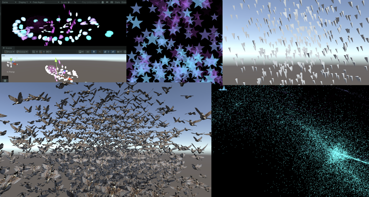

Following the previous article
remoooo: Compute Shader Learning Notes (II) Post-processing Effects
This chapter uses Compute Shader to generate particles. Learn how to use DrawProcedural and DrawMeshInstancedIndirect, also known as GPU Instancing.
Summary of knowledge points:
In addition to being able to process large amounts of data at the same time, Compute Shader also has a key advantage, which is that the Buffer is stored in the GPU. Therefore, the data processed by the Compute Shader can be directly passed to the Shader associated with the Material, that is, the Vertex/Fragment Shader. The key here is that the material can also SetBuffer() like the Compute Shader, accessing data directly from the GPU's Buffer!

Using Compute Shader to create a particle system can fully demonstrate the powerful parallel capabilities of Compute Shader.
During the rendering process, the Vertex Shader reads the position and other attributes of each particle from the Compute Buffer and converts them into vertices on the screen. The Fragment Shader is responsible for generating pixels based on the information of these vertices (such as position and color). Through the Graphics.DrawProcedural method, Unity canDirect RenderingThese vertices processed by the Shader do not require a pre-defined mesh structure and do not rely on the Mesh Renderer, which is particularly effective for rendering a large number of particles.
The steps are also very simple. Define the particle information (position, speed and life cycle) in C#, initialize and pass the data to Buffer, bind Buffer to Compute Shader and Material. In the rendering stage, call Graphics.DrawProceduralNow in OnRenderObject() to achieve efficient particle rendering.

Create a new scene and create an effect: millions of particles follow the mouse and bloom into life, as follows:

Writing this makes me think a lot. The life cycle of a particle is very short, ignited in an instant like a spark, and disappearing like a meteor. Despite thousands of hardships, I am just a speck of dust among billions of dust, ordinary and insignificant. These particles may float randomly in space (Use the "Xorshift" algorithm to calculate the position of particle spawning), may have unique colors, but they can't escape the fate of being programmed. Isn't this a portrayal of my life? I play my role step by step, unable to escape the invisible constraints.
“God is dead! And how can we who have killed him not feel the greatest pain?” – Friedrich Nietzsche
Nietzsche not only announced the disappearance of religious beliefs, but also pointed out the sense of nothingness faced by modern people, that is, without the traditional moral and religious pillars, people feel unprecedented loneliness and lack of direction. Particles are defined and created in the C# script, move and die according to specific rules, which is quite similar to the state of modern people in the universe described by Nietzsche. Although everyone tries to find their own meaning, they are ultimately restricted by broader social and cosmic rules.
Life is full of various inevitable pains, reflecting the inherent emptiness and loneliness of human existence.Particle death logic to be writtenAll of these confirm what Nietzsche said: nothing in life is permanent. The particles in the same buffer will inevitably disappear at some point in the future, which reflects the loneliness of modern people described by Nietzsche. Individuals may feel unprecedented isolation and helplessness, so everyone is a lonely warrior who must learn to face the inner tornado and the indifference of the outside world alone.
But it doesn’t matter, “Summer will come again and again, and those who are meant to meet will meet again.” The particles in this article will also be regenerated after the end, embracing their own Buffer in the best state.
Summer will come around again. People who meet will meet again.

The current version of the code can be copied and run by yourself (all with comments):
Enough of the nonsense, let’s first take a look at how the C# script is written.

As usual, first define the particle buffer (structure), initialize it, and then pass it to the GPU.The key lies in the last three lines that bind the Buffer to the shader operation.There is nothing much to say about the code in the ellipsis below. They are all routine operations, so they are just mentioned with comments.
struct Particle{ public Vector3 position; // Particle positionpublic Vector3 velocity; // Particle velocitypublic float life; // Particle life cycle } ComputeBuffer particleBuffer; // GPU Buffer ... // Init() // Initialize particle array Particle[] particleArray = new Particle[particleCount]; for (int i = 0; i < particleCount; i++){ // Generate random positions and normalize... // Set the initial position and velocity of the particle... // Set the life cycle of the particle particleArray[i].life = Random.value * 5.0f + 1.0f; } // Create and set up the Compute Buffer ... // Find the kernel ID in the Compute Shader ... // Bind the Compute Buffer to the shader shader.SetBuffer(kernelID, "particleBuffer", particleBuffer); material.SetBuffer("particleBuffer", particleBuffer); material.SetInt("_PointSize", pointSize);The key rendering stage is OnRenderObject(). material.SetPass is used to set the rendering material channel. The DrawProceduralNow method draws geometry without using traditional meshes. MeshTopology.Points specifies the topology type of the rendering as points. The GPU will treat each vertex as a point and will not form lines or faces between vertices. The second parameter 1 means starting drawing from the first vertex. particleCount specifies the number of vertices to render, which is the number of particles, that is, telling the GPU how many points need to be rendered in total.
void OnRenderObject() { material.SetPass(0); Graphics.DrawProceduralNow(MeshTopology.Points, 1, particleCount); }Get the current mouse position method. OnGUI() This method may be called multiple times per frame. The z value is set to the camera's near clipping plane plus an offset. Here, 14 is added to get a world coordinate that is more suitable for visual depth (you can also adjust it yourself).
void OnGUI() { Vector3 p = new Vector3(); Camera c = Camera.main; Event e = Event.current; Vector2 mousePos = new Vector2(); // Get the mouse position from Event. // Note that the y position from Event is inverted. mousePos.x = e.mousePosition.x; mousePos.y = c.pixelHeight - e.mousePosition.y; p = c.ScreenToWorldPoint(new Vector3(mousePos.x, mousePos.y, c.nearClipPlane + 14)); cursorPos.x = px; cursorPos.y = py; }ComputeBuffer particleBuffer has been passed to Compute Shader and Shader above.
Let's first look at the data structure of the Compute Shader. Nothing special.
// Define particle data structure struct Particle { float3 position; // particle position float3 velocity; // particle velocity float life; // particle remaining life time }; // Structured buffer used to store and update particle data, which can be read and written from GPU RWStructuredBuffer particleBuffer; // Variables set from the CPU float deltaTime; // Time difference from the previous frame to the current frame float2 mousePosition; // Current mouse position
Here I will briefly talk about a particularly useful random number sequence generation method, the xorshift algorithm. It will be used to randomly control the movement direction of particles as shown above. The particles will move randomly in three-dimensional directions.
This algorithm was proposed by George Marsaglia in 2003. Its advantages are that it is extremely fast and very space-efficient. Even the simplest Xorshift implementation has a very long pseudo-random number cycle.
The basic operations are shift and XOR. Hence the name of the algorithm. Its core is to maintain a non-zero state variable and generate random numbers by performing a series of shift and XOR operations on this state variable.
// State variable for random number generation uint rng_state; uint rand_xorshift() { // Xorshift algorithm from George Marsaglia's paper rng_state ^= (rng_state << 13); // Shift the state variable left by 13 bits, then XOR it with the original state rng_state ^= (rng_state >> 17); // Shift the updated state variable right by 17 bits, and XOR it again rng_state ^= (rng_state << 5); // Finally, shift the state variable left by 5 bits, and XOR it one last time return rng_state; // Return the updated state variable as the generated random number }Basic Xorshift The core of the algorithm has been explained above, but different shift combinations can create multiple variants. The original paper also mentions the Xorshift128 variant. Using a 128-bit state variable, the state is updated by four different shifts and XOR operations. The code is as follows:

// c language Ver uint32_t xorshift128(void) { static uint32_t x = 123456789; static uint32_t y = 362436069; static uint32_t z = 521288629; static uint32_t w = 88675123; uint32_t t = x ^ (x << 11); x = y; y = z; z = w; w = w ^ (w >> 19) ^ (t ^ (t >> 8)); return w; }This can produce longer periods and better statistical performance. The period of this variant is close, which is very impressive.
In general, this algorithm is completely sufficient for game development, but it is not suitable for use in fields such as cryptography.
When using this algorithm in Compute Shader, you need to pay attention to the range of random numbers generated by the Xorshift algorithm when it is the range of uint32, and you need to do another mapping ([0, 2^32-1] is mapped to [0, 1]):
float tmp = (1.0 / 4294967296.0); // conversion factor rand_xorshift()) * tmpThe direction of particle movement is signed, so we just need to subtract 0.5 from it. Random movement in three directions:
float f0 = float(rand_xorshift()) * tmp - 0.5; float f1 = float(rand_xorshift()) * tmp - 0.5; float f2 = float(rand_xorshift()) * tmp - 0.5; float3 normalF3 = normalize(float3(f0, f1, f2)) * 0.8f; // Scaled the direction of movementEach Kernel needs to complete the following:
Generate particles. Use the random number obtained by Xorshift just now to define the particle's health value and reset its speed.
// Set the new position and life of the particle particleBuffer[id].position = float3(normalF3.x + mousePosition.x, normalF3.y + mousePosition.y, normalF3.z + 3.0); particleBuffer[id].life = 4; // Reset life particleBuffer[id].velocity = float3(0,0,0); // Reset velocityFinally, the basic data structure of Shader:
struct Particle{ float3 position; float3 velocity; float life; }; struct v2f{ float4 position : SV_POSITION; float4 color : COLOR; float life : LIFE; float size: PSIZE; }; // particles' data StructuredBuffer particleBuffer;Then the vertex shader calculates the vertex color of the particle, the Clip position of the vertex, and transmits the information of a vertex size.
v2f vert(uint vertex_id : SV_VertexID, uint instance_id : SV_InstanceID){ v2f o = (v2f)0; // Color float life = particleBuffer[instance_id].life; float lerpVal = life * 0.25f; o.color = fixed4(1.0 f - lerpVal+0.1, lerpVal+0.1, 1.0f, lerpVal); // Position o.position = UnityObjectToClipPos(float4(particleBuffer[instance_id].position, 1.0f)); o.size = _PointSize; return o; }The fragment shader calculates the interpolated color.
float4 frag(v2f i) : COLOR{ return i.color; }At this point, you can get the above effect.

In the previous section, each particle only had one point, which was not interesting. Now let's turn a point into a Quad. In Unity, there is no Quad, only a fake Quad composed of two triangles.
Let's start working on it, based on the code above. Define the vertices in C#, the size of a Quad.
// struct struct Vertex { public Vector3 position; public Vector2 uv; public float life; } const int SIZE_VERTEX = 6 * sizeof(float); public float quadSize = 0.1f; // Quad size
On a per-particle basis, set the UV coordinates of the six vertices for use in the vertex shader, and draw them in the order specified by Unity.
index = i*6; //Triangle 1 - bottom-left, top-left, top-right vertexArray[index].uv.Set(0,0); vertexArray[index+1].uv.Set(0,1 ); vertexArray[index+2].uv.Set(1,1); //Triangle 2 - bottom-left, top-right, bottom-right vertexArray[index+3].uv.Set(0,0); vertexArray[index+4].uv.Set(1,1); vertexArray[index+5].uv.Set(1,0);Finally, it is passed to Buffer. The halfSize here is used to pass to Compute Shader to calculate the positions of each vertex of Quad.
vertexBuffer = new ComputeBuffer(numVertices, SIZE_VERTEX); vertexBuffer.SetData(vertexArray); shader.SetBuffer(kernelID, "vertexBuffer", vertexBuffer); shader.SetFloat("halfSize", quadSize*0.5f); material.SetBuffer("vertexBuffer ", vertexBuffer);During the rendering phase, the points are changed into triangles with six points.
void OnRenderObject() { material.SetPass(0); Graphics.DrawProceduralNow(MeshTopology.Triangles, 6, numParticles); }Change the settings in the Shader to receive vertex data and a texture for display. Alpha culling is required.
_MainTex("Texture", 2D) = "white" {} ... Tags{ "Queue"="Transparent" "RenderType"="Transparent" "IgnoreProjector"="True" } LOD 200 Blend SrcAlpha OneMinusSrcAlpha ZWrite Off .. . struct Vertex{ float3 position; float2 uv; float life; }; StructuredBuffer vertexBuffer; sampler2D _MainTex; v2f vert(uint vertex_id : SV_VertexID, uint instance_id : SV_InstanceID) { v2f o = (v2f)0; int index = instance_id*6 + vertex_id; float lerpVal = vertexBuffer[index].life * 0.25f; o .color = fixed4(1.0f - lerpVal+0.1, lerpVal+0.1, 1.0f, lerpVal); o.position = UnityWorldToClipPos(float4(vertexBuffer[index].position, 1.0f)); o.uv = vertexBuffer[index].uv; return o; } float4 frag(v2f i) : COLOR { fixed4 color = tex2D( _MainTex, i.uv ) * i.color; return color; }In the Compute Shader, add receiving vertex data and halfSize.
struct Vertex { float3 position; float2 uv; float life; }; RWStructuredBuffer vertexBuffer; float halfSize;Calculate the positions of the six vertices of each Quad.

//Set the vertex buffer // int index = id.x * 6; //Triangle 1 - bottom-left, top-left, top-right vertexBuffer[index].position.x = p.position.x-halfSize; vertexBuffer[index].position.y = p.position.y-halfSize; vertexBuffer[index].position.z = p.position.z; vertexBuffer[index].life = p.life; vertexBuffer[index+1].position.x = p.position.x-halfSize; vertexBuffer[index+1].position.y = p.position.y+halfSize; vertexBuffer[index+1].position.z = p .position.z; vertexBuffer[index+1].life = p.life; vertexBuffer[index+2].position.x = p.position.x+halfSize; vertexBuffer[index+2].position.y = p.position.y+halfSize; vertexBuffer[index+2].position.z = p.position.z; vertexBuffer[index+2].life = p.life; //Triangle 2 - bottom-left, top-right, bottom-right // // vertexBuffer[index+3].position.x = p.position.x-halfSize; vertexBuffer[index+3].position.y = p.position.y-halfSize; vertexBuffer[index+3].position.z = p.position.z; vertexBuffer[index+3].life = p.life; vertexBuffer[index+4].position.x = p.position.x+halfSize; vertexBuffer[index+4].position.y = p.position.y+halfSize ; vertexBuffer[index+4].position.z = p.position.z; vertexBuffer[index+4].life = p.life; vertexBuffer[index+5].position.x = p.position.x+halfSize; vertexBuffer[index+5].position.y = p.position.y-halfSize; vertexBuffer[index+5].position.z = p.position.z; vertexBuffer[index+5].life = p.life;Mission accomplished.

Current version code:
In the next section, we will upgrade the Mesh to a prefab and try to simulate the flocking behavior of birds in flight.

Flocking is an algorithm that simulates the collective movement of animals such as flocks of birds and schools of fish in nature. The core is based on three basic behavioral rules, proposed by Craig Reynolds in Sig 87, and is often referred to as the "Boids" algorithm:


Think about it, which of the above three rules is the most difficult to implement?
Answer: Separation. As we all know, calculating collisions between objects is very difficult to achieve. Because each individual needs to compare distances with all other individuals, this will cause the time complexity of the algorithm to be close to O(n^2), where n is the number of particles. For example, if there are 1,000 particles, then nearly 500,000 distance calculations may be required in each iteration. In the original paper, the author took 95 seconds to render one frame (80 birds) in the original unoptimized algorithm (time complexity O(N^2)), and it took nearly 9 hours to render a 300-frame animation.
Generally speaking, using a quadtree or spatial hashing method can optimize the calculation. You can also maintain a neighbor list to store the individuals around each individual at a certain distance. Of course, you can also use Compute Shader to perform hard calculations.

Without further ado, let’s get started.
First download the prepared project files (if not prepared in advance):
Then add it to an empty GO.

Start the project and you'll see a bunch of birds.

Below are some parameters for group behavior simulation.
// Define the parameters for the crowd behavior simulation. public float rotationSpeed = 1f; // Rotation speed. public float boidSpeed = 1f; // Boid speed. public float neighbourDistance = 1f; // Neighboring distance. public float boidSpeedVariation = 1f; // Speed variation. public GameObject boidPrefab; // Prefab of Boid object. public int boidsCount; // Number of Boids. public float spawnRadius; // Radius of Boid spawn. public Transform target; // The moving target of the crowd.Except for the Boid prefab boidPrefab and the spawn radius spawnRadius, everything else needs to be passed to the GPU.
For the sake of convenience, let’s make a foolish mistake in this section. We will only calculate the bird’s position and direction on the GPU, and then pass it back to the CPU for the following processing:
... boidsBuffer.GetData(boidsArray); // Update the position and direction of each bird for (int i = 0; i < boidsArray.Length; i++){ boids[i].transform.localPosition = boidsArray[i].position; if (!boidsArray[i].direction.Equals(Vector3.zero)){ boids[i].transform.rotation = Quaternion.LookRotation(boidsArray[i].direction); } }The Quaternion.LookRotation() method is used to create a rotation so that an object faces a specified direction.
Calculate the position of each bird in the Compute Shader.
#pragma kernel CSMain #define GROUP_SIZE 256 struct Boid{ float3 position; float3 direction; }; RWStructuredBuffer boidsBuffer; float time; float deltaTime; float rotationSpeed; float boidSpeed; float boidSpeedVariation; float3 flockPosition; float neighborDistance; int boidsCount;
[numthreads(GROUP_SIZE,1,1)]
void CSMain (uint3 id : SV_DispatchThreadID) { … // Continue below }
First write the logic of alignment and aggregation, and finally output the actual position and direction to the Buffer.
Boid boid = boidsBuffer[id.x]; float3 separation = 0; // Separation float3 alignment = 0; // Alignment - direction float3 cohesion = flockPosition; // Aggregation - position uint nearbyCount = 1; // Count itself as a surrounding individual. for (int i=0; iThis is the result of having no sense of boundaries (separation terms), all individuals appear to have a fairly close relationship and overlap.

Add the following code.
if(distance(boid.position, temp.position)< neighborDistance) { float3 offset = boid.position - temp.position; float dist = length(offset); if(dist < neighborDistance) { dist = max(dist, 0.000001) ; separation += offset * (1.0/dist - 1.0/neighbourDistance); } ...1.0/dist When the Boids are closer together, this value is larger, indicating that the separation force should be greater. 1.0/neighbourDistance is a constant based on the defined neighbor distance. The difference between the two represents how much the actual separation force responds to the distance. If the distance between the two Boids is exactly neighborDistance, this value is zero (no separation force). If the distance between the two Boids is less than neighborDistance, this value is positive, and the smaller the distance, the larger the value.

Current code: https://github.com/Remyuu/Unity-Compute-Shader-Learn/blob/L4_Flocking/Assets/Shaders/SimpleFlocking.compute
The next section will use Instanced Mesh to improve performance.
First, let's review the content of this chapter. In both the "Hello Particle" and "Quad Particle" examples, we used the Instanced technology (Graphics.DrawProceduralNow()) to pass the particle position calculated by the Compute Shader directly to the VertexFrag shader.

DrawMeshInstancedIndirect used in this section is used to draw a large number of geometric instances. The instances are similar, but the positions, rotations or other parameters are slightly different. Compared with DrawProceduralNow, which regenerates the geometry and renders it every frame, DrawMeshInstancedIndirect only needs to set the instance information once, and then the GPU can render all instances at once based on this information. Use this function to render grass and groups of animals.

This function has many parameters, only some of which are used.

Graphics.DrawMeshInstancedIndirect(boidMesh, 0, boidMaterial, bounds, argsBuffer);What is this argsBuffer? This parameter is used to tell Unity which mesh we want to render and how many meshes we want to render! We can use a special Buffer as a parameter.
When initializing the shader, a special Buffer is created, which is labeled ComputeBufferType.IndirectArguments. This type of buffer is specifically used to pass to the GPU so that indirect drawing commands can be executed on the GPU. The first parameter of new ComputeBuffer here is 1, which represents an args array (an array has 5 uints). Don't get it wrong.
ComputeBuffer argsBuffer; ... argsBuffer = new ComputeBuffer(1, 5 * sizeof(uint), ComputeBufferType.IndirectArguments); if (boidMesh != null) { args[0] = (uint)boidMesh.GetIndexCount(0); args[ 1] = (uint)numOfBoids; } argsBuffer.SetData(args); ... Graphics.DrawMeshInstancedIndirect(boidMesh, 0, boidMaterial, bounds, argsBuffer);Based on the previous chapter, an offset is added to the individual data structure, which is used for the direction offset in the Compute Shader. In addition, the direction of the initial state is interpolated using Slerp, 70% keeps the original direction, and 30% is random. The result of Slerp interpolation is a quaternion, which needs to be converted to Euler angles using the quaternion method and then passed into the constructor.
public float noise_offset; ... Quaternion rot = Quaternion.Slerp(transform.rotation, Random.rotation, 0.3f); boidsArray[i] = new Boid(pos, rot.eulerAngles, offset);After passing this new attribute noise_offset to the Compute Shader, a noise value in the range [-1, 1] is calculated and applied to the bird's speed.
float noise = clamp(noise1(time / 100.0 + boid.noise_offset), -1, 1) * 2.0 - 1.0; float velocity = boidSpeed * (1.0 + noise * boidSpeedVariation);Then we optimized the algorithm a bit. Compute Shader is basically the same.
if (distance(boid_pos, boidsBuffer[i].position) < neighborDistance) { float3 tempBoid_position = boidsBuffer[i].position; float3 offset = boid.position - tempBoid_position; float dist = length(offset); if (distThe biggest difference is in the shader. This section uses a surface shader instead of a fragment. This is actually a packaged vertex and fragment shader. Unity has already done a lot of tedious work such as lighting and shadows. You can still specify a vertice.
When writing shaders to make materials, you need to do special processing for instanced objects. Because the positions, rotations and other properties of ordinary rendering objects are static in Unity. For the instantiated objects to be built, their positions, rotations and other parameters are constantly changing. Therefore, a special mechanism is needed in the rendering pipeline to dynamically set the position and parameters of each instantiated object. The current method is based on the instantiation technology of the program, which can render all instantiated objects at once without drawing them one by one. That is, one-time batch rendering.
The shader uses the instanced technique. The instantiation phase is executed before vert. This way each instantiated object has its own rotation, translation, and scaling matrices.
Now we need to create a rotation matrix for each instantiated object. From the Buffer, we get the basic information of the bird calculated by the Compute Shader (in the previous section, the data was sent back to the CPU, and here it is directly sent to the Shader for instantiation):

In Shader, the data structure and related operations passed by Buffer are wrapped with the following macros.
// .shader #ifdef UNITY_PROCEDURAL_INSTANCING_ENABLED struct Boid { float3 position; float3 direction; float noise_offset; }; StructuredBuffer boidsBuffer; #endifSince I only specified the number of birds to be instantiated (the number of birds, which is also the size of the Buffer) in args[1] of DrawMeshInstancedIndirect of C#, I can directly access the Buffer using the unity_InstanceID index.
#pragma instancing_options procedural:setup void setup() { #ifdef UNITY_PROCEDURAL_INSTANCING_ENABLED _BoidPosition = boidsBuffer[unity_InstanceID].position; _Matrix = create_matrix(boidsBuffer[unity_InstanceID].position, boidsBuffer[unity_InstanceID].direction, float3(0.0, 1.0, 0.0)); #endif }The calculation of the space transformation matrix here involvesHomogeneous Coordinates, you can review the GAMES101 course. The point is (x,y,z,1) and the coordinates are (x,y,z,0).
If you use affine transformations, the code is as follows:
void setup() { #ifdef UNITY_PROCEDURAL_INSTANCING_ENABLED _BoidPosition = boidsBuffer[unity_InstanceID].position; _LookAtMatrix = look_at_matrix(boidsBuffer[unity_InstanceID].direction, float3(0.0, 1.0, 0.0)); #endif } void vert(inout appdata_full v, out Input data) { UNITY_INITIALIZE_OUTPUT(Input, data); #ifdef UNITY_PROCEDURAL_INSTANCING_ENABLED v.vertex = mul(_LookAtMatrix, v.vertex); v.vertex.xyz += _BoidPosition; #endif }Not elegant enough, we can just use homogeneous coordinates. One matrix handles rotation, translation and scaling!
void setup() { #ifdef UNITY_PROCEDURAL_INSTANCING_ENABLED _BoidPosition = boidsBuffer[unity_InstanceID].position; _Matrix = create_matrix(boidsBuffer[unity_InstanceID].position, boidsBuffer[unity_InstanceID].direction, float3(0.0, 1.0, 0.0)); #endif } void vert(inout appdata_full v, out Input data) { UNITY_INITIALIZE_OUTPUT(Input, data); #ifdef UNITY_PROCEDURAL_INSTANCING_ENABLED v.vertex = mul(_Matrix, v.vertex); #endif }Now, we are done! The current frame rate is nearly doubled compared to the previous section.


Current version code:

What we need to do in this section is to use the Animator component to grab the Mesh of each keyframe into the Buffer before instantiating the object. By selecting different indexes, we can get Mesh of different poses. The specific skeletal animation production is beyond the scope of this article.
You just need to modify the code based on the previous chapter and add the Animator logic. I have written comments below, you can take a look.
And the individual data structure is updated:
struct Boid{ float3 position; float3 direction; float noise_offset; float speed; // not useful for now float frame; // indicates the current frame index in the animation float3 padding; // ensure data alignment };Let's talk about alignment in detail. In a data structure, the size of the data should preferably be an integer multiple of 16 bytes.
Without padding, the size is 36 bytes, which is not a common alignment size. With padding, the alignment is 48 bytes, perfect!
private SkinnedMeshRenderer boidSMR; // Used to reference the SkinnedMeshRenderer component that contains the skinned mesh. private Animator animator; public AnimationClip animationClip; // Specific animation clips, usually used to calculate animation-related parameters. private int numOfFrames; // The number of frames in the animation, used to determine how many frames of data to store in the GPU buffer. public float boidFrameSpeed = 10f; // Controls the speed at which the animation plays. MaterialPropertyBlock props; // Pass parameters to the shader without creating a new material instance. This means that the material properties of the instance (such as color, lighting coefficient, etc.) can be changed without affecting other objects using the same material. Mesh boidMesh; // Stores the mesh data baked from the SkinnedMeshRenderer. ... void Start(){ // First initialize the Boid data here, then call GenerateSkinnedAnimationForGPUBuffer to prepare the animation data, and finally call InitShader to set the Shader parameters required for rendering. ... // This property block is used only for avoiding an instancing bug. props = new MaterialPropertyBlock(); props.SetFloat("_UniqueID", Random.value); ... InitBoids(); GenerateSkinnedAnimationForGPUBuffer(); InitShader(); } void InitShader(){ // This method configures the Shader and material properties to ensure that the animation playback can be displayed correctly according to the different stages of the instance. Enabling or disabling frameInterpolation determines whether to interpolate between animation frames for smoother animation effects. ... if (boidMesh)//Set by the GenerateSkinnedAnimationForGPUBuffer ... shader.SetFloat("boidFrameSpeed", boidFrameSpeed); shader.SetInt("numOfFrames", numOfFrames); boidMaterial.SetInt("numOfFrames", numOfFrames); if (frameInterpolation && !boidMaterial.IsKeywordEnabled("FRAME_INTERPOLATION")) boidMaterial.EnableKeyword("FRAME_INTERPOLATION"); if (!frameInterpolation && boidMaterial.IsKeywordEnabled("FRAME_INTERPOLATION")) boidMaterial.DisableKeyword("FRAME_INTERPOLATION"); } void Update(){ ... // The last two parameters: // 1. 0: Offset into the parameter buffer, used to specify where to start reading parameters. // 2. props: The MaterialPropertyBlock created earlier, containing properties shared by all instances. Graphics.DrawMeshInstancedIndirect( boidMesh, 0, boidMaterial, bounds, argsBuffer, 0, props); } void OnDestroy(){ ... if (vertexAnimationBuffer != null) vertexAnimationBuffer.Release(); } private void GenerateSkinnedAnimationForGPUBuffer() { ... // Continued }In order to provide the Shader with Mesh with different postures at different times, the mesh vertex data of each frame is extracted from the Animator and SkinnedMeshRenderer in the GenerateSkinnedAnimationForGPUBuffer() function, and then the data is stored in the GPU's ComputeBuffer for use in instanced rendering.
GetCurrentAnimatorStateInfo to obtain the state information of the current animation layer for subsequent precise control of animation playback.
numOfFrames is determined using the power of two that is closest to the product of the animation length and the frame rate, which can optimize GPU memory access.
Then create a ComputeBuffer to store all vertex data for all frames. vertexAnimationBuffer
In the for loop, bake all animation frames. Specifically, play and update immediately at each sampleTime point, then bake the mesh of the current animation frame into bakedMesh. And extract the newly baked Mesh vertices, update them into the array vertexAnimationData, and finally upload them to the GPU to end.
// ...continued from above boidSMR = boidObject.GetComponentInChildren (); boidMesh = boidSMR.sharedMesh; animator = boidObject.GetComponentInChildren (); int iLayer = 0; AnimatorStateInfo aniStateInfo = animator.GetCurrentAnimatorStateInfo(iLayer); Mesh bakedMesh = new Mesh(); float sampleTime = 0; float perFrameTime = 0; numOfFrames = Mathf.ClosestPowerOfTwo((int)(animationClip.frameRate * animationClip.length)); perFrameTime = animationClip.length / numOfFrames; var vertexCount = boidSMR.sharedMesh.vertexCount; vertexAnimationBuffer = new ComputeBuffer(vertexCount * numOfFrames, 16); Vector4[] vertexAnimationData = new Vector4[vertexCount * numOfFrames]; for (int i = 0; i < numOfFrames; i++) { animator.Play(aniStateInfo.shortNameHash, iLayer, sampleTime); animator.Update(0f); boidSMR.BakeMesh(bakedMesh); for(int j = 0; j < vertexCount; j++) { Vector4 vertex = bakedMesh.vertices[j]; vertex.w = 1; vertexAnimationData[(j * numOfFrames) + i] = vertex; } sampleTime += perFrameTime; } vertexAnimationBuffer.SetData(vertexAnimationData); boidMaterial.SetBuffer("vertexAnimation", vertexAnimationBuffer); boidObject.SetActive(false);In the Compute Shader, maintain each frame variable stored in an individual data structure.
boid.frame = boid.frame + velocity * deltaTime * boidFrameSpeed; if (boid.frame >= numOfFrames) boid.frame -= numOfFrames;Lerp different frames of animation in Shader. The left side is without frame interpolation, and the right side is after interpolation. The effect is very significant.

A good title can get more recommendations and followers
void vert(inout appdata_custom v) { #ifdef UNITY_PROCEDURAL_INSTANCING_ENABLED #ifdef FRAME_INTERPOLATION v.vertex = lerp(vertexAnimation[v.id * numOfFrames + _CurrentFrame], vertexAnimation[v.id * numOfFrames + _NextFrame], _FrameInterpolation); #else v.vertex = vertexAnimation[v.id * numOfFrames + _CurrentFrame]; #endif v.vertex = mul(_Matrix, v.vertex); #endif } void setup() { #ifdef UNITY_PROCEDURAL_INSTANCING_ENABLED _Matrix = create_matrix(boidsBuffer[unity_InstanceID].position, boidsBuffer[unity_InstanceID].direction, float3(0.0, 1.0, 0.0)); _CurrentFrame = boidsBuffer[unity_InstanceID].frame; #ifdef FRAME_INTERPOLATION _NextFrame = _CurrentFrame + 1; if (_NextFrame >= numOfFrames) _NextFrame = 0; _FrameInterpolation = frac(boidsBuffer[unity_InstanceID].frame); #endif #endif }It was not easy, but it is finally complete.

Complete project link: https://github.com/Remyuu/Unity-Compute-Shader-Learn/tree/L4_Skinned/Assets/Scripts
When rendering points which gives the best answer?

What are the three key steps in flocking?

When creating an arguments buffer for DrawMeshInstancedIndirect, how many uints are required?

We created the wing flapping by using a skinned mesh shader. True or False.

In a shader used by DrawMeshInstancedIndirect, which variable name gives the correct index for the instance?